PID tuning woes

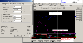
after i had started the trend i was kicking myself for not adding the decant tank to the trend.


Don't kick yourself: it's a step function and it can be easily seen from the data where the decant starts and stops; although it will be nice to have it in the next trend.
 
Last edited:
[PV] scaling is the same as it has always been like shown in post #116 [i.e. 0-4096]

Oh dear. I understand your reluctance to correct that mistake (of your predecessor), but we can work around it.

That being the case, saying "Kp is too small" is easily the understatement of the week. All we have done by reducing the Loop Update Time (Configuration tab) is lowered the gain on (i.e. de-fanged) the Integral feedback, without replacing it with any Proportional feedback.

I guess the question is, for @MaxK: what PV scaling is implicit in that Kp = 12.5, Ki = 0.0078 tuning for Tank/Pump 1?
 
I guess the question is, for @MaxK: what PV scaling is implicit in that Kp = 12.5, Ki = 0.0078 tuning for Tank/Pump 1?

Of course you right Kp = 12.5, Ki = 0.0078 is wrong for OP’s scaling.

What units of measurement are mentioned in the first post?

PI input in feet’s, PI output in Hertz. In other words if setpoint – 2.5, PV=3,5 then E= 3,5-2,5=1 ft. Then PI out = 12.5 Hz/ft * 1 ft + Ui(i-1) + 0.0078 Hz/(ft*sec) 1 ft * dt
 
More simulations

Caveat: this model is similar to OP's system but it runs 500x faster (12h cycle in 86.4s), so it is the relative magnitudes of Kp and Ki that are in view here; the absolute magnitudes are meaningless.


========================================================================
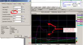
Case Kp = 100, Ki = 50: similar to most recent trend from OP i.e.

  • level overshoots when decant starts,
  • then undershoots and still undershot when decant ends,
  • at which point the flow is high to compensate for the negative error,
    • which amplifies response to drop in inflow as decant ends.
  • Note the low level before recovery
    • this will come up again in the final case.
kp100_ki50.png

========================================================================
Case Kp = 1000, Ki = 50: increased Kp by an order of magnitude.

  • More like P-only case
  • Stable level offset achieved quickly
    • before I-action has time to accumulate
    • so overshoot is less
  • Slow to return to setpoint
kp1000_ki50.png

========================================================================
Case Kp = 1000, Ki = 200: increased Kp by an order of magnitude from first case; increased Ki by a factor of four.

  • Again like a P-only case
  • With a bit more I-action to drive level to setpoint sooner.
kp1000_ki200.png
========================================================================
Case Kp = 1000, Ki = 200: increased Kp by two orders of magnitude from first case; increased Ki by an order of magnitude.

  • Again like a P-only case
  • Ki increase probably not needed
kp10000_ki1000.png
========================================================================
Case Kp = 100, Ki = 50: handles undershoot manually with a single parameter change

  • Same tuning as first case
  • Offset bias was originally 50
  • When level started dropping fast from undershoot,
    • offset bias was manually decreased by 5%
      • probably around 10-15gpm
    • which immediately shored up the level
      • preventing low level alarm, and
      • sped up the return to a stable level at setpoint with the base load and much less oscillation.
kp100_ki50_stop_level_drop_with_bias.png
 
Of course you right Kp = 12.5, Ki = 0.0078 is wrong for OP’s scaling.

What units of measurement are mentioned in the first post?

PI input in feet’s, PI output in Hertz. In other words if setpoint – 2.5, PV=3,5 then E= 3,5-2,5=1 ft. Then PI out = 12.5 Hz/ft * 1 ft + Ui(i-1) + 0.0078 Hz/(ft*sec) 1 ft * dt


PI output range is 0-100 corresponding to 0-60Hz. How that relates to flow in gpm is more complex, but a delta of 75gpm corresponds to a delta of 35% for Pump 1 and a delta of 40% for Pump 2, and those are non-linear.
 
Post #2 still applies and hasn't been refuted.


lol, agreed, and as I've stated several times.

but it hasn't been believed (understood?), apparently, either, and I even explained it with a spreadhsheet fer pete's sake, I'm out of ideas, so ...

Popcorn!
 
Last edited:
It takes around 40minutes, from ~08:00 when the decant cycle starts and the level was somewhat steady, for the flow at ~100gpm (4-wells base load, no decant) to increase to 115gpm (decant load) at ~08:35, at which point net flow is 0 and the level is not changing.

Over that time, the level initially increases by 1.7ft-, from 2.3ft+ to 4.0ft.

By the end of the decant flow (115gpm), because the level has not recovered and has instead almost completed its first oscillation, it is ~1.98 and increasing.

Although the relative conditions are not identical to when the decant flow started, when the decant flow stops I would expect a similar initial swing with the level decreasing by 1.7ft (or so, maybe more, maybe less, but in that neighborhood), which would almost certainly pull the level below the 1ft low limit.

Increasing Kp will increase the flow more quickly as the level rises, which will attenuate the level rise, which in turn will attenuate the Integral Accumulation, which in turn will mean the level will not need to go as low to eliminate the excess Integral Accumulation.

P.S. Yes, I am groaning with you, @Peter, that I explain it this way, but I don't think throwing the Laplace domain, which is of course the right thing to do, at OP is going to help here.

Maybe we could set up a Jupyterlab page to simulate this, with time-domain and s-/Laplace-domain (complex-plane, IIRC?) plots. Once validated (although the model is so simple, that should be trivial), OP could tweak the gains to see that there is no way to improve on the optimal poles.

so if i understand what you are sayin, im screwed with the tools i have available?

Post #2 still applies and hasn't been refuted.I went to the store and forgot to buy more popcorn :( I did buy more beer :)

maybe i misunderstood, but the P only approach wouldnt work because of the PID was a continuous task, not periodic.
 
so if i understand what you are sayin, im screwed with the tools i have available?

I'll probably regret it, but...

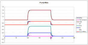
Look at the P-only+Bias chart. Up to 100 seconds Level = SP,=1 Bias= CV(Outflow)=Inflow=0,7, Error=0, Proportional term Up=0

A very important point that you must understand:
The level is the flow mismatch integral (i.e. the flow mismatch is accumulates)

Back to chart
At the 100th second, the inflow increases from 0.7 to 0.9. Flow mismatch appears -> level increases (accumulates flow mismatch) -> Error increases -> proportional term Up=Kp*E increases -> CV (Outflow) = Bias + Up increases. At some error value (in the example 0.6 Kp=0.33) CV (Outflow) = inflow, i.e. flow mismatch = 0 -> Level become stable. Obviously, the larger the Kp, the smaller the error (E= Flow mismatch/Kp, theoretically Kp->infinity E->0).

PROPORTIONAL TERM MAKES LEVEL STABLE
If it is not necessary to achieve setpoint level, it is not necessary to use integral term

Look at the PI chart
The proportional term still compensates for the flow mismatch. Integral term Ui slowly compensates level.

Thus, the proportional term solves the main problem and should be dominant, I still think it could be multiplying the current Kp value by at least 5-10 times.


P.S. Is the Proportional and Integral terms values available? It would be possible to try the PI controller idiotic tuning algorithm

P_bias.png PI.png
 
Caveat: this reply is based on a combination of reading documentation, reading what OP wrote, and my empirical experience.

As you understand, the question was addressed to another person, but thank you very much for your answer.

Am I correct in understanding that the if actual level error = 1 ft then E% = 100%/4095 = 0.02442% ?
i.e. OP applies Kp = 12.5* 0.02442 = 0.305 per ft, Ki = 0.0078*0.02442*500/5.5 = 0,0173 per ft sec?

Yes, I am pretty sure that is correct; the 5.5ms is an estimate, but it is certainly somewhere between 0 and 6.856ms.

It's great to work with people who have a sense of proportion ;).
 
Last edited:
so if i understand what you are sayin, im screwed with the tools i have available?

No, not at all, not in the slightest, couldn't be further from the truth.


mobil1syn;931422 maybe i misunderstood said:
a continuous task, not periodic.

No, we stated the exact opposite, several times, and explicitly. I suggest that, next time the process is in between decants with a steady level, spend some of that 8h reading the entire thread, carefully, and list anything that is not clear. Almost everything here requires no more than grade school math, an understanding of the discrete PLC scan cycle, and a sense of proportion. This ain't rocket science.

TL;DR

The reason the PI approach is giving problems is that the actual loop update time is different than the PID Loop Update Time parameter (Configuration tab), and the reason that actual loop update time is different is that the PID is in a continuous task.

Once you assign 0 to the value of Ki (i.e. use P-only feedback control), the difference between the actual and PID parameter values for the loop update time becomes irrelevant.

Have you looked at the explanation of what the PID instruction does? It is not a black box: it behaves in a deterministic way each time it is executed with its input rung being True. If we set the Ki and Kd values both to 0, the PID executes P-only feedback control, equivalent to a linear function (y = m x + b), i.e. CV% = Kp E% + OutputBias%.
 
Last edited:

Similar Topics

Hello, I am attempting to tune a PID loop on a process. The process involves a valve with electronic actuator that has quite a high deadband...
Replies
10
Views
2,193
Hi everyone, yet another PID problem. I'm hoping I understand enough of the process I'm controlling that my request for help is reasonable. If a...
Replies
113
Views
28,148
A few months ago, I started to look into PID controllers and the tuning of first order processes. This has, partly thanks to you, resulted in a...
Replies
162
Views
62,467
I haven't had to tune a PID loop in a very long time. It's actually a PI loop for a pulse width modulation s.v. What was the name of that tuning...
Replies
16
Views
4,117
Hello, there is anyone who have already used hpmont plc? now i am programming for that plc and have " pid autotuning is not working" issue. I have...
Replies
0
Views
978
Back
Top Bottom