Tuning PID loop - dealing with valve deadband and high sensitivity

ryangriggs

Lifetime Supporting Member
Join Date
Jun 2016
Location
USA
Posts
198
Hello, I am attempting to tune a PID loop on a process. The process involves a valve with electronic actuator that has quite a high deadband: approx 2-3% of total valve range.


The valve is set up to divert flow from a pipe if the pipe's flow rate exceeds a setpoint.


The valve output is very sensitive, causing large changes in main pipe flow when the position is changed by a very small amount (1% or less).


Due to these factors, I'm finding that the process oscillates when attempting to modulate low flow rates, as only a couple percentage points of change in position will basically cut off the flow or wildly overshoot. It seems to work reasonably well at higher flow rates, however.


Does anyone have any tips for tuning the PID loop in such a case, and/or designing around a high deadband?


Thanks!
 
Are you sure that your problem is a deadband?

I presume in case "modulate low flow rates" PID gain * valve gain became too large to plant current state.

I would suggest that you describe the process in more detail and in which cases the system is stable and in which it is not.
 
Another system designed by incompetent engineers.
Actually 2-3% isn't bad. From what is said the valve needs to change from 3% to 4% which is an extremely small range. A smaller valve would be better.
What is bad is that 1% causes such a change in the flow.

It is time for drbitboy to start pulling teeth.
I got a new popcorn maker and some new buttery spray for the pop corn.
 
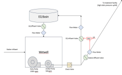
Hello, here's a detailed description of the process. It is a wastewater lift station with gravity influent and force main effluent, as well as a local EQ basin and requisite valves/flow meters.

Diagram:
5gy2

GOAL:
Split effluent flow between EQ basin and Force Main (Station Effluent), modulating based on Station Effluent max flow rate.


For example: Station Effluent Max Flow Rate = 200gpm
- EQ Influent Valve should modulate so that station effluent flow rate never exceeds 200GPM (all excess flow is directed to EQ basin.


We can't use the Station Effluent valve to control this flow, because the static pressure on the force main is much greater than the pressure of the EQ influent line, due to its elevation. Therefore, if the EQ Influent valve is opened with no pump running, flow reverses in the force main and drains the force main.


Therefore we can only open the EQ Influent valve while pump(s) are running, and then only slightly. When a Jockey Pump is running, this valve usually modulates to about 15% open to accommodate flow above 200gpm. When a Duty Pump is running, it wildly oscillates between 35% and 0% trying to regulate the Station Effluent to 200gpm. However, it works fine (no oscillation) at flow rates of 1000+ gpm when Duty Pumps are running. It also works fine (no oscillation) at 200gpm setpoint with a Jockey Pump running.


I am using AB CompactLogix PLC with RSLOGIX 5000. The analog flow rates and valve position feedback values update a few times per second.
I'm using the PID instruction with the following parameters:

Jockey Pump Running:
P = 10.0
I = 0.1
D = 0.001
Update Rate: 1 second

Duty Pump Running:
P = 2.0
I = 0.1
D = 0.001
Update Rate: 1 second
 
Last edited:
And why do you need PID on both "Duty Pump" and "Jockey Pump"?
This diagram seems as Buster Pump Station, and I think that you can't have both PID for flow and PID for pressure.
 
Hello, here's a detailed description of the process ...


When a Duty Pump is running, it wildly oscillates between 35% and 0% trying to regulate the Station Effluent to 200gpm.


However, it works fine (no oscillation) at flow rates of 1000+ gpm when Duty Pumps are running.


Can you reconcile those two statements?

Where is the 1+kgpm flowing to or from in the second case?

It seems to me you may be actually regulating the pressure at the bottom of the Station Effluent line*, but using the Station Effluent flowmeter as a proxy for that pressure.

If there is a deadband (I assume that means hysteresis) in the EQ Influent Valve actual position wrt the CV (commanded position), you are probably up the creek. Say the "correct" position is 3%: with 2% hysteresis you will not get that 3% position until the CV is 5%, after which point there will also be some reset windup as the station eff flow lags, so maybe the valve will get to 3.5% on a CV of 5.5%. However, now that there is EQ infl flow, the pressure will drop quickly, however the valve will not move until the CV gets to 1.5%, which is 4% below where it stopped, and by the time it gets there, there will be significant reset built up (the pressure and Station Effl flow will be low) in the other direction, so it will overshoot in the other direction.

The point is that the effect of the hysteresis in valve position (~2%) at flow rates near 200gpm is a large fraction of the ideal valve position (a few %), so the process is highly non-linear so it is never going to do good control with a straight PID. At higher flowrates it is still non-linear, but much less so relative to the valve position.

One way to get around this might be to implement a model of the CV-to-valve-position relationship, specifically keeping track of whether the PID CV was last increased or decreased and whether that actually moved the valve, so the PLC have a model of the actual valve position, and know how to mung (add or subtract an offset to) the CV into a signal that will put the actual valve at the PID CV output value. I have a vague recollection of someone on the forum (maybe @Tom Jenkins?) who did this.

I am not sure that will help: I expect the system gains when the EQ Effl valve first opens near a total flow of 200gpm is very different from when the total flow is 1+kgpm, so the tuning parameters for one situation will not work with another.

* I assume the Station Effluent Valve position is fixed, because you said you cannot use it to control flow
 
Did I draw the control loop (red) correctly?
I.e. the lower the SP, the more the valve opens. Correct?


If Jockey Pump Running:
U_P (i) = 10.0 * Error(i)
U_I (i) = U_I (i-1) + 0.1 * 1 sec * Error(i)
U_D (i) = 0.001 *( Error(i)- Error(i-1))/ 1 sec
U_PID = U_P + U_I + U_D

If Duty Pump Running:
U_P (i) = 2.0* Error(i)
U_I (i) = U_I (i-1) + 0.1 * 1 sec * Error(i)
U_D (i) = 0.001 *( Error(i)- Error(i-1))/ 1 sec
U_PID = U_P + U_I + U_D

Correct?


How long does it take for the EQ influent valve to go from fully closed to fully open?

It would be useful to see PV, CO, SP, valve position curves in cases:
Jockey Pump is running SP = 200gpm.
Duty Pump is running SP = 200gpm.
Duty Pump is running SP = 1000+gpm.

FC.png
 
Ditto what drbitboy said about hysteresis. A dead band is not a problem because the valve is only flowing one way.

I don't understand the two pumps in series. How can the duty pump pump 1500+ gpm through a 500 gpm pump. Why have a 1500 gpm if the output needs to be 200 gpm? The designer must have been nuts.
The pressure change of pressure at the output of the jocky pump will greatly affect the the flow through the EQ influent valve. No one seems to take this into consideration. A simple PID will not hack it and it is non-linear because the flow is proportional to the square root of the pressure difference between the output of the jockey pump ant the EQ basin pressure which I assume is at atmospheric. In the end, the Station influent can't be greater than the Station Effluent or the EQ basin and Wetwell will over flow or leak.

Bad design.
 
I missing something.

I attached curves of the process model as I understood it #8 (values have nothing to do with reality)

Everything is exactly the opposite:

At the beginning, when the station effluent is high (QT influent valve is almost closed) the gain of the plant is high, + deadband - the process is oscillatory.

As the station effluen decreases (QT influent valve opens) The gain of the plant decreases and the process becomes smooth.

Either I misunderstood the process or I'm intrigued

vlv.png
 
Is valve butterfly valve or ball valve?
Butterfly have very narrow operation range if compared to ball valve which is designed to control.


Poor design.
 

Similar Topics

Hello Everyone, I have a fast PID loop that I was having issues with tuning it. - The CV is a sliding stem valve - The PV is a High pressure...
Replies
36
Views
24,067
Hi all, splitting out from this thread because it's a somewhat different question to the original. I have to migrate some code from a Micrologix...
Replies
17
Views
4,112
Long time listener, first time caller. I have a Micro850 PLC controlling the temperature in seven fermentation vessels at a local brewery. Each...
Replies
2
Views
2,607
I am using PID instruction in RS Logix 5000 with independent equation. I am confused about its tuning. Please somebody explain under listed...
Replies
1
Views
4,932
Hi all, I'm working on this small batching project and this is my first time when i have to develop PID loop tuning screen on my HMI. I was just...
Replies
0
Views
1,698
Back
Top Bottom