FX3U clone problem uploading a code with gx works2

For learning purposes it is somehow ok, but you should keep in mind that even original FX3U capabilities are quite obsolete now. FX3U is over two decades old PLC.

Yep, and it's still now a revolution for me because I don't know any ladder programming.

So the plan is to do the project, do all the required programming and the wanted results + HMI addition is a good step in the project development.

This clone should be enough for this project.

As for graduation project, I can't comprehend how is it allowed by university to use clones. I know that Mitsubishi is donating it's equipment to universities, so it would be much better option.

We aren't a university, we are a corporation that run a lot of technical colleges in Saudi Arabia, I don't know if I can contact Mitsubishi to tell them that I'm an employee in an educational institution and we want a PLC or two for our projects lab.

Universities should learn engineers how to think, and how to put priority on safety and intellectual property.

Yeah but this stuff is safe, it's a controller, where could be the problem ?

You even don't need real equipment for learning, as GxWorks has excellent simulator.

Yeah, I know the simulator is a good route, but in the projects course we must use hardware, kit, wiring, soldering, etc. It's not a theory class.
 
I wrote a ladder code, and I want to print the code, so I can post it here.

How to extract the code from gx works 2 ?
 
The best way is to print it to a PDF file & post that.
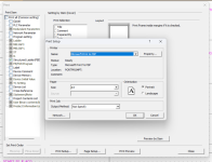
Select print preview, suggwest you untick some of the things not really wanted I only tick the lad/fbd etc. then in print setup select print to pdf then attach files on this post (at the bottom) load the file & thats it.

Print.png
 
Yep thank you so much parky.

This is my first self developed inefficient ladder example but it worked :)

Then I immediately found a more better blink example in the official FX3U programming manual.

Now I started to learn something about ladder programming.

So it's basically a sequential process to the END statement. But of course every program must have a continuous looping system.

So what is the standard loop design in ladder programming ? Is it a jump statement or what exactly ?
 
you don't, the PLc starts at rung 0, through to the end, then loops back, you don'y have to do anything the actual process (generally) is before the scan of the main program the PLC does a bit of houskeeping, i.e. scans real inputs 7 transfers them to the input image, runs the program you have written then at the end updates the real outputs from the internal output image then perhaps does other things like communications etc.
Some Modern PLC's now have the ability to update the I/O imidiately rather than wait til the start of scan, you can also write subroutines that when called in your program jump to that subroutine, process it then jumps back to where it left off.
You can also loop back to a rung of logic a few times (care is needed becouse for safety, PLC's have a watchdog timer so if it exceeds the scan time (usually in milliseconds) then it put the PLC into stop & turns outputs off.
There are many processes going off in the background besides your code, timed interrupts for high speed processing, input interrupts, special I/O cards that need processing may be by an interrupt or outside the scan of your program, I suggest you scan the internet & watch some of the many PLC videos out there.
 
you don't, the PLc starts at rung 0, through to the end, then loops back, you don'y have to do anything the actual process (generally) is before the scan of the main program the PLC does a bit of houskeeping, i.e. scans real inputs 7 transfers them to the input image, runs the program you have written then at the end updates the real outputs from the internal output image then perhaps does other things like communications etc.

OK, I thought PLC systems run almost exactly like microcontrollers. Even the microcontrollers code has an OS, it's dependent. Some times there might be an OS and some times there isn't.

But from your explanation, I think PLCs have a different system than embedded systems. And every PLC program must run on an OS even if there's no code.

The PLC will run the same OS every time from scanning to processing the main program.

Some Modern PLC's now have the ability to update the I/O imidiately rather than wait til the start of scan

What is the difference between "the new ability to update the I/O" and "the ordinary system scan" ?

Is that called initial state of inputs/outputs that the programmer has set to be processed before anything ?

you can also write subroutines that when called in your program jump to that subroutine, process it then jumps back to where it left off.

Yeah, I know this is called system interrupts.

But I have no much experience about the processors used in PLC, are they single core, dual cores or maybe more.

But if it's a single core, then yes the system will stop, run that interrupt sub-routine, then come back to main program. If it's more than a single core, then that means the system will continue to run and the other core should take care of that interrupt sub-routine.


You can also loop back to a rung of logic a few times (care is needed becouse for safety, PLC's have a watchdog timer so if it exceeds the scan time (usually in milliseconds) then it put the PLC into stop & turns outputs off.

Why the looping back is time sensitive since it's part of the main program ? I mean if I want to jump to a specific part of the program. Or you still mean the interrupt sub-routine ?

Either if it's an interrupt sub-routine or normal main program jump, if anyone of these actions is time sensitive, then it's not about the ladder programming. I think PLC standards are critical because it's meant for industrial and commercial purposes. That's my guess.

There are many processes going off in the background besides your code, timed interrupts for high speed processing, input interrupts, special I/O cards that need processing may be by an interrupt or outside the scan of your program, I suggest you scan the internet & watch some of the many PLC videos out there.

I absolutely will. Actually the reason I got back to PLCs is the use of this clone. It's beautiful how something can force me to learn about a complete different area than what I'm used to.

I know you mean here the OS of a standard professional PLC.

Thank you so much for your time parky :)
 
What I really like to understand now is the set of data structure in ladder programming.

Like what is prefixed with X is an input, Y is output.
M is internal data registers, C counters.

Another ones that is labeled as M8200 means: Switching
relay. What is switching relay ?

What else ? are there other data structures ?
 
you need to visit the Mitsubishi website, & download the different pdf's for the FX there you will find information on the different internal bata i.e. M for bits, D for registers, T for timers, C for counters.
The D registers & M bits 8000 onwards are not generally user bits but standard bits/registers for example M8013 is a one second clock so you can use that in your program as a contact but not as an output coil in other words it is turned on every second by the PLC operating system.
some are used for special add on cards etc.
to answer some of your questions it does has a sort of OS specifically dedicated to that PLC it is what does all the work, although not every PLC will work this way but many have a mini interpreter so for example your code is actually a set of hex codes i.e. perhaps a normally open contact in ladder is say H2B4F the interpreter knows that the hex code is a normally open contact for say M30.
No idea in Mitsubishi exactly what the structure is but in siemens it works this way the upper byte is the instruction type & the lower byte is the address of that contact, so in some respect it works like basic i.e. it interprets the ladder into instructions so no need to compile (although it does compile of sorts, it stores the ladder as these instructions). the ladder is just the way to display it in on the PC. some PLC's do actually compile it but perhaps not in the same way as some computer programs.
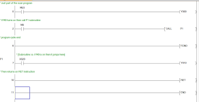
Attached is what the statement list looks like of the ladder above.
Most PLC Manufacturers keep their actual code & how it works a secret
As for interrupts it will depend on the PLC but most update the I/O either at the end of program scan or before the scan, there are instructions to update any time i.e. somewhere in the program scan as many times as you want, AB (Rockwell) do apparently do it asyncronously i.e. perhaps any time an input or output is processed in your logic or whatever.

compiled.png
 
Last edited:
you need to visit the Mitsubishi website, & download the different pdf's for the FX there you will find information on the different internal bata i.e. M for bits, D for registers, T for timers, C for counters.
The D registers & M bits 8000 onwards are not generally user bits but standard bits/registers

I did actually, most of the files about the hardware specs, but the one about programming is 900 pages. And I found good examples and in the section:
2.5 Introduction of Devices Constructing PLC

They are describing these structures. I should've read this file earlier, I think everything is described in this file.

Relationship-among-devices.png


Then the description about the system hardware:

without-attached-memory-cassette.png


I think this is the reason of the problem I got earlier with the clone PLC, which I think doesn't have a "memory-cassette".

not-use-the-built-in-program-memory.png


This picture explains what "memory-cassette" contains. Which the clone won't have.


for example M8013 is a one second clock so you can use that in your program as a contact but not as an output coil in other words it is turned on every second by the PLC operating system.
some are used for special add on cards etc.

I'm trying to understand the other system devices.

I know x is input, y output, t timers, c counters, k literal values, m data registers holding logic values and d data registers holding number values.

And learned just now that h for hexadecimal vlaues, e for floating values.

There are still other types which are Index registers (V)(Z) and Pointers (P)(I). But it's not important now I can cover them later.
 
There is very little need for a memory cassete, the FX3U comes as standard now with 16K ram, that is a lot of programming, the clones is probably only 8k if that.
index registers "Z" index register is used as a pointer for example to indirectly address either a bit or register, it is used as a pointer so if you move 10 into Z then use M100Z in your program it actualy uses M110 i.e. an offset of 10.
So by incrementing "Z" in say a loop then the next M100Z will be M111 & so on.
There are a number of Z registers Z0-xx (depends on the PLC) using just Z automatically picks Z0. same for D registers if Z0 is 20 & you use D30Z0 then it points to D50.
Pointers are used to jump to subroutines that are after the FEND instruction (you have to program that in before the END instruction).

pointer.png
 
There is very little need for a memory cassete,

What is memory cassete ? is it a supporting memory beside program memory ?


the FX3U comes as standard now with 16K ram, that is a lot of programming, the clones is probably only 8k if that.

Yep, the specs of this clone is that the program memory is 8k. I actually didn't change anything in the PLC parameter settings. Should I change anything for this clone in the PLC parameter settings beside changing the memory capacity ?

index registers "Z" index register is used as a pointer for example to indirectly address either a bit or register, it is used as a pointer so if you move 10 into Z then use M100Z in your program it actualy uses M110 i.e. an offset of 10.
So by incrementing "Z" in say a loop then the next M100Z will be M111 & so on.
There are a number of Z registers Z0-xx (depends on the PLC) using just Z automatically picks Z0. same for D registers if Z0 is 20 & you use D30Z0 then it points to D50.
Pointers are used to jump to subroutines that are after the FEND instruction (you have to program that in before the END instruction).

I'm new to ladder programming language, and I've been working these weeks in doing some basic programs; input, output, counters, timers, set and reset. But I faced today a problem with analog input/output to get it working, I will open a new thread about it.

Also, pointers I think I have some idea of what they are good for, I have a little bit of C programming experience, I know pointers offer accessibility to other data in another different locations. I don't know if it's the same in ladder programming.
 
The memory cassete is just additional memory, you can choose to have the program stored on the internal memory or on the cassete so there is no need, also there is a thing called file memory "R" registers, you can create a file register either in internal memory or on a cassete (not sure the clones support the cassete anyway.
Most clones you cannot change the PLC Parameters as I stated before, yours may be different but the ones I have seen you cannot change them so the memory size & other parameters are fixed.
The index registers are very similar to C programming, it depends on how you are programming the clone i.e. if using pure ladder (GXDeveloper or GXWorks in LAD compatible mode) then you use the Z registers directly i.e. D123Z0
If you use GXWorks in a structured FBD/LAD mode then you use it much like C programming. i.e. you create a pointer say call it My_Pointer & possibly give it a real address such as D20 then to use that pointer you simply put it in brackets like
shown in the attached code.
 
I'm looking at a China knock off PLC Controller Industrial Control Board 24V 5W FX3U-48MR-407 for the purpose of learning/training on. Any idea if these are ok? My use would be narrowed down to 2 or 3 analog pressure transmitters for regulating water pressure and also being able to control VFD's to ramp up booster pumps (simulating multi pump domestic water booster pumps in multi story commercial buildings. Also is the Mitsubishi programming software available for free to program these things? What are the limitations/weaknesses with these cheap knockoffs?
 
I'm looking at a China knock off PLC Controller Industrial Control Board 24V 5W FX3U-48MR-407 for the purpose of learning/training on. Any idea if these are ok?
My use would be narrowed down to 2 or 3 analog pressure transmitters for regulating water pressure and also being able to control VFD's to ramp up booster pumps (simulating multi pump domestic water booster pumps in multi story commercial buildings.
First of all they are cheap, and it works. The model you mentioned I think has more than what you need.

Also is the Mitsubishi programming software available for free to program these things?
The Mitsubishi programming software is free.

What are the limitations/weaknesses with these cheap knockoffs?
Well, to my experience, it has a shutdown protection circuit, if a short circuit happened, the PLC shut-off with the power supply.

As for the limitations, there's one or more instructions which this clone doesn't support.
 

Similar Topics

Hi, I tried today to get RD3A and WR3A instructions to work on the PLC and it didn't work, but it worked in simulation. I followed the clone...
Replies
18
Views
1,419
I'm a beginner in the automation field and I've set up an automation system connecting several devices (datalogger, radio, etc.) via Modbus RS485...
Replies
5
Views
217
Hi All, want to ask. I have PLC a programme to control the valve. The existing programme is to control valve A (Y22), and I want to change to...
Replies
2
Views
145
Dear all, I don't know why setup of password became challenging and weird. After setting up the password and try to upload the ladder from the plc...
Replies
3
Views
178
Dear all, I have fx3u series plc with built in rs422 port and usb-sc09-fx cable. I have a a hyperterminal like application to send and receive...
Replies
8
Views
230
Back
Top Bottom