Current Meter Recommendations

afm

Member
Join Date
Aug 2023
Location
Tennessee
Posts
88
Hi all,

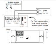
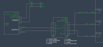
I have been working on a project that requires me to measure the current across a 90 VDC motor of a medical device (similar to an elliptical) to distinguish between machine and user work. Currently I have been doing this with an AC current transducer (Automation Direct ACT050-42L-F) and an I/O link analog display for my PLC to read (IFM DP2200). I have been having a very difficult time with data collection/predictive modeling with the given system I have as there is a lot of noise in the data. For example if I start my device I will see a 6.40mA on my analog display. If I leave it running for 10 minutes and check again I will see 5.90 mA. Or if I stop the machine and start it a few hours later without changing any parameters/settings (speed, step length, etc.) then I will see a different reading, hence I have no reliable "baseline" to reference.

I spoke with Automation Direct on recommendations to add to the system design or circuitry to improve this/reduce noise; they believe the current transducer being used may be contributing to the noise due to the sensitivity of the inductance (with temperature, cable jacket, mounting, etc.) as these work like fluke meters. I was recommended to use a current meter or something similar for more sensitive/stable readings.

This brings me to my question, has anyone dealt with a similar issue with their current transducers? Almost all transducers have this style, so does anyone have any recommendations on alternatives? I found this AE001Current sensor with IO-Link (AC current sensors with IO-Link - autosen.com) that is similar but seems to clamp down on the wire and had IO-link so an additional sensor wouldn't be necessary, however I am not sure how much of an improvement this would make. Any advise is greatly appreciated.
 
I have adopted the project from another group, so have been using their selected components/circuitry without questioning it up until this point, which was a mistake on my part. The motor is on a DC drive (attached), and the transducer is on one of the motor cable wires (A1 terminal) which is for the motor's armature voltage (which is 90 VDC according to the datasheet), so this is likely one of my issues since its a AC transducer...

I spoke with the original designer for the system and they said that the transducer should be used to measure the input (AC) side and selected it because they have never used DC transducers for speed control motors. I am new to working with transducers, but would switching the transducer to the L1 wire change anything with the output I see currently from the sensor?

Or is the best measuring tool to achieve a more sensitive, stable current reading going to be a DC current transducer on the A1 terminal? (like https://cdn.automationdirect.com/static/specs/acuampdcs100.pdf)
 

Attachments

  • Motor Driver.PNG
    Motor Driver.PNG
    149.2 KB · Views: 24
  • Motor Driver Transducer.PNG
    Motor Driver Transducer.PNG
    68.8 KB · Views: 24
The AC CT on the DC drive input will probably work pretty well for that simple DC drive, but monitoring the motor current with the DC Accuamp CT might be better. Since you already have the AC CT, if you get the DC CT and use them both, you could answer that question definitively for future readers.
 
Can't tell as pic is blurry and you didn't list the model, but does the AC/DC converter drive possibly have a signal out that can be configured to monitor current.
 
For example if I start my device I will see a 6.40mA on my analog display. If I leave it running for 10 minutes and check again I will see 5.90 mA
This doesn't seem unreasonable as the resistance in the windings will increase as they warm up. Check the documentation for the duration of this warm-up phase.

Keep in mind these are mV devices and therefore sensitive to noise so if you're not using one with a built-in transmitter, make sure you've got twisted pairs and the shield wire is connected properly.
 
The AC CT on the DC drive input will probably work pretty well for that simple DC drive, but monitoring the motor current with the DC Accuamp CT might be better. Since you already have the AC CT, if you get the DC CT and use them both, you could answer that question definitively for future readers.
I made the swap of moving the AC CT from A1 to L1 and saw slightly better/stable measurements. I got a DC CT (DCT100-42-24-F) that I'll compare with it soon.

Check TruMeter
Home - Trumeter

These meters have a lot of config options and come with 4-20ma out.
I am using a MTPM-001-1L18 which has F.L. Amps of 10.4, we don't get close to the full load, but these CT have a 5A range. But these are nice to eliminate analog convertor sensors, thanks for sharing.
 
Can't tell as pic is blurry and you didn't list the model, but does the AC/DC converter drive possibly have a signal out that can be configured to monitor current.
From what I know about this drive, it does not unfortunately, it is a MGC403-11-00MD DC drive for a MTPM-001-1L18 motor.

This doesn't seem unreasonable as the resistance in the windings will increase as they warm up. Check the documentation for the duration of this warm-up phase.

Keep in mind these are mV devices and therefore sensitive to noise so if you're not using one with a built-in transmitter, make sure you've got twisted pairs and the shield wire is connected properly.
Good point, we use Igus CF130-UL for the motor cable which has no shielding (I initially had the transducer on A1 with this cable wire. And use an M12 cordset from the AC CT screw terminals to the analog display (attached).

I have not found any info on this warm up phase, but it has caused me some troubles with predictability for my motor's current. Every time I change the machine settings (speed, step length, etc.) I must "scan" the sensor for a few seconds to establish what the machine's baseline is, so I have a reference when checking if there is work done by a user on the system, not sure how other technologies get around this to achieve similar functions.

1709059351554.png
 
Realize that the AC input current is only proportional to the DC output current at one given speed/output voltage setting.

Power In (VA) = Power Out, so running at 10% output speed/voltage will show a much lower AC current at full torque than it will at 100% speed.
 
I got a DC CT from automation direct (https://www.automationdirect.com/ad...-a-_dc)/dc_current_transducers/dct100-42-24-f) to try out, but the lowest sensing range is 0-50A which is a bit high, but I will see how it does. I will check these out for lower sensing ranges, so thank you for the recommendation.

I want to test it out but likely have a simple circuitry issue. I wired it as shown in the attached image and my sensor display was unresponsive. My wiring for the AC CT was correct; my AC CT only had a +/- output terminal, and the DC has +/- Power and +/- Output terminals. The wiring from analog sensor to PLC had remained the same since it worked well with my AC CT, so I would guess my wiring from the analog sensor to the DC CT has an issue. What have I mixed up? Thanks in advance!

For reference I am using an IFM DP2200 analog display and and X20DS4387 IO-link module with my DCT100-42-24-F and ACT050-42L-F.
 

Attachments

  • ACCT.PNG
    ACCT.PNG
    29.9 KB · Views: 13
  • DCCT.PNG
    DCCT.PNG
    35.2 KB · Views: 13
I just tried to wire my DC CT like my AC CT, and removed the +/- Power pins, and my analog display read "OL" open loop and started to blink "SC1". I wired my +24V and GND wires back to the PSU terminal blocks and get the blank screen again on my display. Should I be using my PLC module for the CT power (brown wire) and the PLC module ground for the CT ground (black wire)? Then what would be my output + and - wires? I know this is likely a simple mix up but help is appreciated.
 

Attachments

  • DC CT specs.PNG
    DC CT specs.PNG
    29.2 KB · Views: 13
Hi all,

Just a update on this... I have still been unsuccessful with this DC current transducer. I get a "nPrb" display on my display which is for no sensor recognized. I attached the wiring diagram that both the CT sensor manufacturer and the analog display manufacturer confirmed were good.

I can confirm that the DCT is receiving +24V and I have tried reversing cable direction. I also tried breaking the circuit to test the output on the sensor. I have +Power, -Power, and -OUT connected to the DCT like shown in the diagram, and connected my multimeter in series between the white wire(4-20mA) and the +OUT terminal, I get a reading of 1.6 mA DC. Have I received a faulty sensor if my outputs are not in the 4-20 range? Is there any other test I should do to verify this? Thanks in advance.
 

Attachments

  • DC CT 3.5.PNG
    DC CT 3.5.PNG
    93.2 KB · Views: 15

Similar Topics

I purchased a 4-20ma AC Current Transducer, it can be set to 0-100a, 0-150a, 0-200a. It is not True-RMS. This is connected to a panel meter and I...
Replies
1
Views
1,486
Dear experts, i have a CT 600/5A and analog Amps meter 0-600A @2.5Class, 1)now i want to measure the same current to changing analog meter to...
Replies
1
Views
2,407
My current project involves instrumentation for AC current. Input current range is 0-5 A (AC). Output of the device to be used has to be 4-20 mA...
Replies
2
Views
3,165
Today I was working on my project for school and we were using a power supply with 24V and we accidentally had the current at 0.9A. We heard a pop...
Replies
9
Views
551
HI i have a delta VFD M-series in the manual, in order to enter the motor rated current you set the parameter P,52 =the motor rated current my...
Replies
7
Views
667
Back
Top Bottom