Using a Safety Relay with a Flame Detection Sensor

kdcui

Lifetime Supporting Member
Join Date
Dec 2007
Location
USA
Posts
386
I have an application where I want to use a safety relay in combination with a flame detector as the sensing element. The flame detector has relay contact outputs, so I'd like to use those in combination with a safety relay to complete the safety function. This is the only safety function on the system, and I would like to avoid using a safety PLC for cost and complexity reasons (chief amount them, the requirement around now needing lifecycle management around the safety PLC / safety application program - which can be onerous). This is considered a low-demand process application.

Internally we are following IEC 61511 (since this system is a process application) but this is not really an SIS, so we are falling somewhere in between machine safety and process safety.

However, most if not all safety relays I have seen are really geared toward machine safety, and all the application examples show E-Stops and Guard doors. So I get the feeling what I am trying to do may not be that common?

The dilemma I am running into is that we are targeting a SIL2 application.
Most safety relays are capable up to SIL3 or SIL2.
The sensor I am looking at can achieve SIL2 with the relay contact outputs., but these relays outputs are only single channel. So even if the individual devices themselves meet the overall failure rate / probability requirements for the safety loop, I am having trouble finding data the support the architectural constraint requirements.

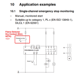
All the application examples of safety-relays, using a single channel, can only achieve SIL1 due to the lack of diagnostic coverage - but these examples are all for things like Estops and Guard Switches. In my case, I have plenty of DC on the sensor. My gut tells me I am OK but I do need to document and prove the safety function can achieve the target level - just unsure how to do this given my example.

I've attached an image from a Phoenix Contact 2963763 relay datasheet (with my edits).

Long story short:
I am trying to set up a safety function for flame detection using safety relays instead of a safety PLC, and want to ensure I am not barking up the wrong tree.
 

Attachments

  • 2024-02-29-09.10.42.png
    2024-02-29-09.10.42.png
    72.9 KB · Views: 26
Does the flame detector have analog output (4-20MA) that is SIL2 capable? If so, perhaps 4-20MA out to a SIL2 capable limit controller with 2 complementary relay contacts to the safety relay?
 
Does the flame detector have analog output (4-20MA) that is SIL2 capable? If so, perhaps 4-20MA out to a SIL2 capable limit controller with 2 complementary relay contacts to the safety relay?

Thanks. Yes it does have a 4-20mA signal. My plan was to use this as non-safety feedback at the PLC. Initially I looked at something like this:
MACX MCR-SL-UI-REL - Limit value switch

But this only converts the 4-20mA signal to a contact output. I still need something to de-energize and monitor a reset condition. The whole goal here was to get something simple that does not require the use of programming software to configure, otherwise the lifecycle management requirements get more stringent because it is considered a safety "application program" in the eyes of IEC 61511.

Do you have a example limit controller you could link to for reference?
 
Is it possible to use a second flame detector, to have 2 chanels for safety relay
It is, but I'd have to either a) wire these sensors in series through a single channel or b) wire them as single channel through a relay that requires 2 enabling inputs (2 separate single channel inputs).

I do not believe I can put two separate sensors in parallel (and wire them as a dual channel device) unless they are physically part of the same device (like a dual channel E-Stop), because the differences in timing the rising / falling edge on the contacts will trip the safety relay.
 
In regards to flame detection safety circuits, you have to meet certain requirements and have to go through your safety department, maintenance, plant engineering and then get it approved by the state authority AND your insurance company. this is what we had to do when we had to upgrade our system in 2005.
i was not involved with the project, but my supervisor told me what all had to be done.
james
 
If the topic deals with gas or other fuel burners, you should first be informed of the regulations applicable to these types of installations at the installation site, that is, to the safety of the combustion part in which it is normally not enough to have a flame detector relay, since it is mandatory to have control over the presence of air, the fuel pressure or the air sweep time before ignition.
There are usually devices on the market that control the ignition cycle and flame control.
 
they do make configurable safety relays, the AB one is programmable through free software too. Its PN starts with 440C something, I'm sure other programable safety relays can do similar things, that's simply an example
 
If the topic deals with gas or other fuel burners, you should first be informed of the regulations applicable to these types of installations at the installation site, that is, to the safety of the combustion part in which it is normally not enough to have a flame detector relay, since it is mandatory to have control over the presence of air, the fuel pressure or the air sweep time before ignition.
There are usually devices on the market that control the ignition cycle and flame control.
This...we always use FireEye controllers for burners for this reason.
 
I did just this in a room of hot presses heated with oil run through an oil boiler - although the manufacturer kept saying it wasn't a boiler it was a burner and they have even had to argue with OSHA inspectors because that would open them to boilermaker requirements.

I installed in the room 4 UV/IR flame detectors, but they all had 2 channel safety and an auxiliary relay output. They were wired to their own safety relay on the main operator station with an OKAY and RESET indicators, the Reset was also the reset pushbutton.

You said your sensors were SIL2, but if they aren't 2 channel output I don't think they could be.
 
I've found that manufacturers seem to be very loose in defining devices as Sil2 and Sil3. Phoenix has a smart contactor they claim as Sil 3....with one contact and no feedback. I believe they are using the MTBF numbers as a means to classify SIL. I know enough about safety to be dangerous, but if it's not redundant failure points I don't define anything as SIL2, much less SIL3.
 
I've found that manufacturers seem to be very loose in defining devices as Sil2 and Sil3.
I'm not an expert, but I do know SIL requirements do not allow any manufacturer to use their own interpretation of the specific requirements

Otherwise Bubba Mfg located in his brother's garage would be making SIL3 items for nuclear power plants
 

Similar Topics

Hello, I am new to programming plcs and putting the hardware together and would like get advice on how to do this for a Micrologix 1000 project...
Replies
2
Views
4,603
Hi all, I'm working on a safety circuit and had some question about fusing. Incoming supply - 120V/15A Power supply - PSL-24-060...
Replies
5
Views
590
Howdy everyone, I have a project that i am duplicating on an older version of the same cell. With all the additional stuff that has been added the...
Replies
3
Views
1,004
I was just using 3TK safety modules from Siemens or other brands and I had no problem with them. I always recommended my customers to use them...
Replies
7
Views
2,351
Can someone help me? I am having trouble differentiating between category 3, and category 4 safety circuits. Could someone tell me what qualifies...
Replies
28
Views
15,243
Back
Top Bottom