TIA Portal - working with rate of change

sp_

Member
Join Date
Sep 2023
Location
Niagara Falls
Posts
9
I am working on a PLC program that requires an analog valve to close a given percentage in a given time in seconds. I give the start position, the final position, and the time. I calculate the rate of change and I add that to the start position every second until it reaches the final position. For example, the start position is 0%, the final position is 50%, time is 5s. So the rate of change = (50-0)/5 = 10%/s. So every second I add 10% to the current position of the valve until it equals the final position and then it stops. This becomes tricky when the rate of change has many decimals or a recurring decimal and using the equal to comparator. for example, the start position is 0%, the final position is 40%, time is 7s. the rate of change = (40-0)/9 = 4.444444...%/s. The current position is never exactly equal to the final position and the logic keeps executing infinitely and the valve is either fully open or fully closed. I have tried a few different things such as rounding the numbers or using limits instead of equal to, but none of it seems to be working perfectly.
Is there a better way to do this?
Thanks!
 
Just thinking "out loud" here, but can you add a check where you take the final position minus the current position and if it's less than your increment, just go straight to the final position?
Or, before sending the command to the valve, compare it to the desired end point. If what you calculated is >= the desired setpoint, just overwrite it with the desired setpoint.


edit:
I guess both would have the same effect, it's just a question of which way is easier to implement into your existing code.
 
One of the problems with floating point maths, there will mainly be an error it is one of the problems with the accuracy, you can reduce the number of decimal places there was an old post here where I showed the logic to give 2 decimal places this tends to reduce the error in floating point maths, In reality, never use an = for floating point maths because of this either use >= or <= or perhaps a range.
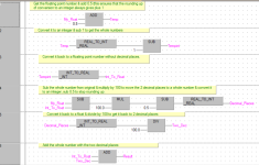
Attached, is a sample of reducing it to 2 decimal places but could be for any i.e. 3 or 4.
One problem of course is removing decimal places is the preceeding decimal place for example if you have a number 1234.567894 reducing it to 2 depends on the boundary around 5 if 5 or above add 1 to the preceeding decimal or less than 5 do not add.

Two dec places.png
 
So at the beginning of the movement, you take the desired final valve opening value, and the time to move, and calculates a rate of change per second. After that every second you add this value to the analog output.
If that is so, then yes you will get rounding errors.
You can minimize the rounding error by not adding a new value to the previous value (that will sum up the rounding error). Instead, calculate the value based on how much time has expired multiplied by the rate of change factor.
Then use a suitable tolerance (using min and max limits) on the analog value to know when to stop.
Fairly simple, I dont see why it shouldnt work.


edit: The above also assumes that the time can only be set in whole seconds, since you say that every second you update the analog value.
If that is not so, use my suggestion of calculating the analog value besed on the currently spent time multiplied by the factor. Then you dont need to only do the calculation every second, just do it constantly in every PLC cycle.
 
Last edited:
fractional percentages are pointless.

do everything in integers and do what @joseph_e2 said: take the smaller of the amount remaining and the amount per step.

also, comparing REAL numbers with an EQU instruction is recipe for disaster, as OP notes. use either a GEQ or LEQ or LIM instruction (Allen-Bradley) to compare so you know when you are within 0.00000x.
 
Let me suggest a different approach that eliminates floating-point math: constant integral step size; variable step period. Caveat: this assumes the TIA timer is "good enough."

So for 0% to 40% in 9s (4.444%/s), change by 1% every 225ms, i.e. 225ms is the step period, or by 4% every 900ms. The step period can be rounded up or down to account for typical timer inaccuracies and/or when the calculated value has non-zero fractional milliseconds, if needed, or a form of the Bresenham Algorithm could be used to adjust the step time on the fly.

Sidebar: does TIA not have a ramp function? Or is TIA "some assembly required," as usual? [Update: there is a RAMP FB, in TIA. Does anyone know if it works?]
 
Last edited:
[Update: there is a RAMP FB, in TIA. Does anyone know if it works?]


I've never used it, but my experience with TIA is that 99% of the time the instructions do what they say they do. The trick is that what they say they do and what I think they should do can be very very different things....
 
I also agree about ditching the floating point maths, instead of 0-100% as a float, make it 0-32767 as an integer (or what ever your raw analogue is) As the analogue accuracy can only be as the +- 1 count there would be no problem.
Yes you can use a float for the calc of rate of change but convert it back to an integer the error will be generally within the resolution of the raw analogue.
If you want to use floats then when driving the valve from 0-X% then use >= wnen driving the valve from X-0% use <= due to the float maths error assume 7 decimal places then a target of 50.0% (actual 50.0000000) the reading could jump from 49.9999999 to 50.0000001 so a compare of 50.0 (50.0000000) would be missed.
 
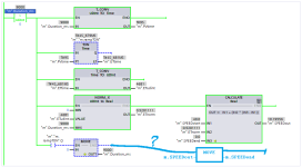
This runs a timer once through the ramp time, instead of the annoying logic Siemens requires to implement a repeating IEC_TIMER, and eliminates the busy calculations in the previous methods suggested.

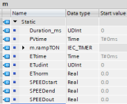
How to assign (HMI?) m.Duration_ms, m.SPEEDend, and m.SPEEDstart is left as an exercise for OP, as is whether OP does not want to update the output speed continuously.

Uses a CALCULATE block, instead of the broken built-in SCALE_X, because, well ... Siemens.
Untitled2.png

Untitled.png
 
Last edited:
Looking at post 10..... I have my answer. No response necessary :)
Touché!
Did you download the LGF and look it over?
My google-fu found the LGF package and the RAMP FB (which I was the first to mention) some days ago; why and whether OP did not find them is less than interesting to me; downloading yet another Siemens (i.e. which seems to be Deutsch for Some - or Much - Assembly Required) package of likely-broken arcana (cf. the SCALE_X block), needing reverse-engineering to obtain a workaround to be actually useful, is also less than interesting :).

If tha' wants summat done right, do it th'self.
 

Similar Topics

Hi, I have now two times experienced that my I/O field is not working on the HMI that I have made. I have several I/O field and some of the are...
Replies
14
Views
7,092
TIA Portal V13 with 1515 Processor. TIA Portal being run on VM. For many weeks, was able to go online and monitor blocks while troubleshooting...
Replies
3
Views
3,984
Hi experts, I would like to have some opinions from you :) I have to estimate working hours using PCS 7 on a quite big project. I am a PCS 7...
Replies
2
Views
2,595
Hello Guys, I am configuring this SCADA and created some new PLC tags. I am not sure why the feature "Synchronize with PLC tags" under the HMI...
Replies
0
Views
4,145
I cannot make a connection that is integrated in the TP900... Could the reason because of using a 300 CPU in Tia Portal ???
Replies
4
Views
1,454
Back
Top Bottom