Tia portal ctu

Karsten

Member
Join Date
Feb 2006
Location
Odense
Posts
158
Hi,

I am confused regarding TIA portal and counters. I use CTU.

I wish to have one counter counting 0-10. When it reaches 10 is shall increase next counter and the first counter starts over.

Easy I figure and use CTU1.QU to both trigger the seccond counter and reset the first. However it seems to reset the first counter before the sceeond is triggered.

What am I doing wrong?
 
The program is executing the network that the CTU is on, so it will instantly reset and cause CTU1.QU to show false by the time the program moves on to the next network.

Try changing it so that in the network below the second counter you have CTU1.QU as the normally open input and CTU1.R as the output assignment.
 
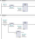
You need to reset the counter after the second one has incremented, not before. I tend not use counters in that situation, but use the INC command instead, and a Comparison so that I know when it has reached my set point. The Comparison increments a second variable and resets the first. I am not sure why they have a (RT) to reset a timer, but not a (CT) to reset a counter. As always with Siemens there will be many other ways of doing this, as others will express their thoughts :)

INC not Count.JPG
 
What am I doing wrong?


That is the right question, because the PLC cares not a whit what you want it to do, but it will mercilessly and inexorably do exactly what you tell it to do.

@Puddle most likely nailed the answer, but may we see your code? That would make it easier to understand what when is actually happening.
 
I do it the same as BryanG, except I dont have the second oneshot.
The second oneshot is superfluous and there is a (small) risk if something else writes a large value to the counter address in the PLC scan after the reset, then the oneshot will not trigger and the counter will forever increment but not reset.
 
Siemens made non-intuitive choices in their counters (see TL;DR below; and similar bad choices in their timers), which is why @BrianG and @JesperMP implement their own counter schemes from atomic instructions.

I think their approach is the way to go, i.e. don't use the broken Siemens counter in this case, because otherwise anyone looking at the code will need to know about the internal implementation of the Siemens counters in order to understand how the program works.

TL;DR

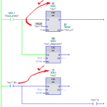
I suspect you are doing something like the following and getting a similar result.

The issue is time, and the scan cycle and the program evaluation are the clocks. A PLC interprets its program "left-to-right and top-to-bottom." And in this case it appears that the Siemens implmentation evaluates the ctu1.QU at the Reset pin of ctu1 immediately after evaluating the rising edge of the primary trigger (Clock_0.5Hz in my case) at the CU pin of ctu1 and incrementing the count from 9 to 10, which puts a 1 into ctu1.QU. So it is as if the ctu1.QU at the ctu1 Reset pin is in a Normally Open Contact instruction on a branch in parallel with, and below (so it is evaluated after i.e. top-to-bottom), the rung/branch of the primary trigger coming into the ctu1 CU pin.

Note that I used a simple ADD, instead of a CTU, for the secondary increment, as that second trigger would only be 1 for one rung even if Siemens had implemented their logic properly.
two_ctus_naive.png
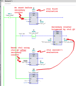
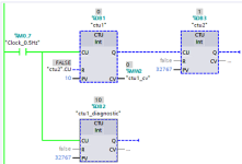
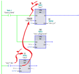
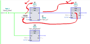
The next image below is one solution around the Siemens counter implementation: buffer the ctu1.QU bit into a reset bit, ctu1_qu, evaluated on a rung after the ctu1 CTU instruction, i.e. between the evaluations of ctu1 CTU on this scan cycle and the next scan cycle.

Note that the ctu1_diagnostic CTU is there only for information i.e. to display what is happening: both ctu1 and ctu1_diagnostic have incremented to 10; ctu1 was reset on the next scan cycle when ctu1_qu (not ctu1.QU) was 1; ctu_diagnostic was not reset, since its Reset pin is held False, and so remains at 10.
two_ctus_buffered_qu.png
An the final image below is one more solution using a single rung, with ctu1.Q'soutput rung triggering the secondary counter*, but still buffering ctu1.QU into ctu1_qu after all pins on ctu1 are evaluated.

* again an ADD as ctu1.Q cannot be 1 for more than one scan
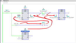
two_ctus_one_rung.png
 
Last edited:
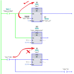
One more working approach to get around the awkward (but consistent!) Siemens counter implementation and to accomplish a simple task:
two_ctus_one_duplicated.png
 
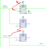
And one more that may be easier to read, but again as always there is the need to reverse-engineer the wonky Siemens implementation. It would not be so bad if they at least made the attempt to document exactly how it works.
two_ctus_inverted.png
 
Last one, perhaps the simplest, but far from best practice:
two_ctus_one_duplicated_alt.png
Correction: earlier I misspelled @BryanG's handle and included him with @JesperMP in eschewing the Siemens CTU in favor of building their own from atomic parts; I was wrong on both counts.
 
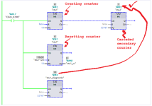
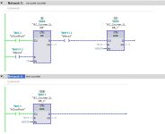
Here's my cascaded counter (with a test counter for comparison) - why do you need to cascade the counters anyway?

countx.jpg
 
Thank you for all answers and suggestions! Interesting that such a simple thing as a counter ok can render so many solutions. I simplified my question since there is more to it than just cascaded counters however now I get the idea.

I believe that Puddles suggestion will be easiest for me to implement without making to much changes. Or is there anything unforeseen that can happen with this solution?


The program is executing the network that the CTU is on, so it will instantly reset and cause CTU1.QU to show false by the time the program moves on to the next network.

Try changing it so that in the network below the second counter you have CTU1.QU as the normally open input and CTU1.R as the output assignment.
 
Or is there anything unforeseen that can happen with this solution?
Originally Posted by Puddle
Try changing it so that in the network below the second counter you have CTU1.QU as the normally open input and CTU1.R as the output assignment.
The issue is not what you do after the first counter, it is what you put on the R input pin of that first counter, ctu1. Towit,

The simplest interpretation of what @Pudddle wrote would be this, which has the same problem i.e. ctu1.QU is reset to 0 before the subsequent rungs evaluate the --[Normally Open ctu1.QU]--(Coil ctu1.R)-- logic:
two_ctus_puddle_00.png
Perhaps we simply write to ctu1.R only and put nothing the R input pin of ctu1? No, that means that the input pin R of ctu1 always has an implicit [False] overwriting ctu1.R, so ctu1 is never reset, and ctu2 will never count past 1 because there will be but one rising edge of ctu1.QU:
two_ctus_puddle_01.png
Well, then how about using ctu1.R's value as the value for that input pin R of ctu1? Success!
two_ctus_puddle_02.png
That works, but if we think about it, ctu1.R is then merely a buffer storing the value of ctu1.QU from the end of one evaluation of ctu1 until the beginning of the next evaluation of ctu1 on the next scan cycle.

That being the case, we could as easily drop the ctu1.R:=ctu1.QU assignment (--] [--( )--), and instead use ctu2.CU as the buffer, because it is also assigned the same value as ctu1.QU at the end of one cycle and maintains it through the start of the next scan cycle:
two_ctus_puddle_03.png
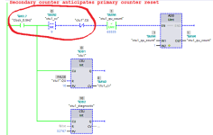
That also works, but one more level of simplification is possible: use the output pin Q of ctu1, which pin's state should represent the same value as ctu1.QU, to drive ctu2's CU pin directly:
two_ctus_puddle_04.png
This is essentially identical to @LD's approach, but drops the Output Coil instruction on the rung connecting the ctu1 and ctu2 CTUs.
 
Last edited:

Similar Topics

Hi All, Someone at work has put a PLC system on my desk, that's just been taken off an idle production line. He said "It's an S7 PLC. We don't...
Replies
10
Views
258
Hi guys , I'm new with Allen Bradley, but I have experience with Tia portal (s7 1200 ,s7 1500) I want to convert my project from Tia portal to...
Replies
2
Views
210
Hi, I have had problem with upgrading some projects from v16 to v18. I tried it on 3 diffrent computers. I want to post this so that anyone that...
Replies
3
Views
176
Hello gentlemen, Im working on a small project on TIA Portal, about establishing a Modbus TCP connection between my ET200SP plc and a socomec...
Replies
12
Views
312
I am currently am in a PLC class and need urgent help on how the ladder logic would be laid out. I understand how to get the traffic lights to...
Replies
19
Views
447
Back
Top Bottom