Need assistance with RS Logix Traffic Light program

ThomasHunter

Member
Join Date
Nov 2021
Location
Ontario
Posts
8
I am a complete newbie to this stuff and wanted to try this out and was looking for any information on how I can complete this by Wednesday evening. Currently taking a college evening course and I am struggling with the PLC portions.

If you are thinking - 'Do you want us to do your assignment for you?'

No. I will be tested in a couple of weeks and have to be left with my skills and knowledge on this subject by creating a program that will not be known to me until test day.
_____________________________________________________________

Assume that the lights are field-wired in parallel so that there is only one PLC address required per stage (i.e. North/South Green, East/West Yellow, Advanced Left Turns, etc.).

Your program must operate the Traffic Light system in an acceptable and safe manner.

Therefore the following must be taken into consideration:

a) The Red Light Stages must overlap by 2 seconds to prevent accidents

b) If the Master Control is manually disengaged at any point during normal operation the Red lights must flash until Master Control is engaged (at which point the lights will operate normally with North/South traffic flowing first)

Overview: https://imgur.com/a/TDJElmO
_____________________________________________________________


Any information is greatly appreciated. The reason for my struggle is that we get no practice sessions and need to plan and build the programs in less than a couple of hours.

Thank you for your time.
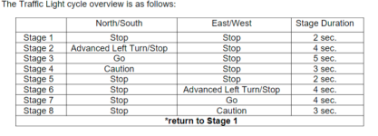
traffic light cycle overview.png
 
Hi, and welcome to the forum!!
You are correct in presuming that the folks here won't do your assignment for you. We will always offer suggestions and direction as long as you show what you've done, where your at and if you're stuck what you've done to get "unstuck"
With that, I wrote a rather complex traffic light program just because it keeps me proficient and sharp in programming and navigation. I get bored at work.
What helped me the most was to go and park somewhere safely near a large intersection and observe exactly how the traffic control system runs it's cycle. Then sit and apply that observation to the hardware/software you have and start from there.
Good luck and I hope this helps. I wish you the best success.
 
I do not have AB and as posted, we will help but not do it for you so here is a suggestion:
Use an integer variable for a step sequence:
i.e. call it Step_No
start at 0 so
-----[ = Step_No 0]------------[TON Timer_1]

Timer_1.DN
----| ]----------------[MOV 1 Step_No]

-----[= Step_No 1]------------[TON Timer_2]

Timer_2.DN
----| ]----------------[MOV 2 Step_No]

& so on when it gets to the final step timer done then move 0 back into Step_No variable
This gives the sequence steps (A good way is actually do in in steps of say 10 so when 0 move 10, then 20, then 30 etc. this gives you an easy way to add extra steps if required at a later date should you need them.
Then to drive the outputs just use compares for example:
If a particular output (say a RED light) on one leg that needs to be on during steps 0 to 4 then use compares like this (greater than or equal or less than or equal)

---[>= Step_Seq 0]------[<= Step_Seq 4 ]---------( ) left Traffic light

Another thing if a particular light needs to be on during steps 0 to 1 & 4 to 5 then it is the same as above but a second double compare ored with the first

---[>= Step_Seq 0]------[<= Step_Seq 1 ]------|--( ) left Traffic light

---[>= Step_Seq 4]------[<= Step_Seq 5 ]------|
 
Assume that the lights are field-wired in parallel so that there is only one PLC address required per stage (i.e. North/South Green, East/West Yellow, Advanced Left Turns, etc.).
As far as I know that's not the way traffic lights work in the real world. So part of the challenge of this assignment will be keeping track of what the instructor wants and how traffic lights actually work.
I guess you'll need a stage 9 to accomodate the need to flash the red lights simultaneously.
Consider using a free running timer that resets itself and a bunch of Greater Than and Less Than instructions to define the stages.
 
As far as I know that's not the way traffic lights work in the real world.
I have seen intersections that largely performed in this manner under normal conditions though I am confident they weren't actually wired in parallel, just programmed to operate that way.

Presumably the instructor feels a more realistic scenario would be too complicated for the level the students are at.


Regarding the actual problem, if the lights are purely time-based (ie no sensors to change the cycle based on actual vehicle presence) then this is quite straightforward. Determine how many different combinations of lights will occur in a cycle, then set up a sequence of steps advanced through by timers.


Turn on lights based on which step you are at, then add logic to disable the sequence and flash the red lights if the master control is disengaged.


(If you set it up right you don't need a separate step for master control disengaged)
 
Last edited:
Just want to say thank you very much for much for the greetings and the amazing information so far.

@parky and @plvlce : Thanks for your suggestions! It is going to get me on the right path. I know it.

Is there some type of simulation software that is similar to RS Logix 5000 that I can download and use on my laptop? I find that would save me a lot of time instead of drawing up the rungs.

Thank you for your time.
 
I have posted this several times.
For any given homework assignment or task at work, you must consider these instructions as the customers specifications.
1. read the specifications several times.
2. write down your understanding of what you read in a step by step fashion.
3. review what you wrote down and see if it makes since, modify if necessary.
4. Get with the mechanical designer and discuss the project openly and honestly. When your opinions differ in regards to an operation, discuss it, don't ignore it.
there must be a reason for a difference of opinion. modify your instructions and i/o to accommodate the mechanical design if possible. Mechanical design may have to be changed due to plc programming limitations.
YOU BOTH MUST be in agreement on all points of operation before going to step 5. you may have to modify/rewrite step 2 and 3 based on the discussion.
5. step through your notes again this time, you are the one following the instructions. In other words, you are the plc. Write down on paper the events you are doing.
For example, turn on hydraulic motor 1, write down hydraulic motor 1 on. If a sensor is needed, write that down.
6. continue through the instructions. When you turn off the motor, mark a line thru it.
7. go through your instructions with all the sensors, motor aux. contacts, outputs documented. Modify if necessary.
8. repeat step 6 until no changes are made.
9. Try to group your data words into some organized fashion. The more programs you write, the more organized you become
10. write the plc program using your notes in a step by step manner.
10A Over half way through writing the program you WILL realize a different/better way of doing something you are almost done writing
(or a new spec will require it) and you will completely rewrite it
10B It WILL happen more than once.
Note: 10A and 10B added to list. thanks Aabeck, member plctalk.net forum


11. DOCUMENT EVERYTHING!!! You may remember things today, but in 5 years and hundreds of programs later, you won't
remember, especially at 2 am, so DOCUMENT EVERYTHING. use easy to understand tags and rung comments.
12. MAINTENANCE is your best friend and your worst enemy.
if you work with them and find out what they can do, write the program where they can trouble shoot the program. they will be able to fix the problem and everyone will be happy.
BUT
if you write the program to where you are the only one who understands what is going on, maintenance can't fix the issue, the machine is down, production is down,
management hears about it, your boss hears about it, then you hear about it - rewrite the program or else. you get calls all hours of the day and night.
this still holds true, a machine can cost a billion dollars, but it's not worth 10 cents if maintenance cannot trouble shoot the issue and fix the issue.
everyone has their own style of programming and you must develop your own way as well.
13. when the customer is in your shop and brings maintenance, discuss things with them, let them see your code, be open.
if they make suggestions, write them down, don't ignore them. their ideas may save you days of programming.
14. install the program and leave in program mode if possible so you can to debug your i/o
15. when writing your instruction manual(s), use your notes from step 9. Use easy to understand English language. specify the i/o, timers, counters, outputs when possible.
this will help maintenance even more to see what is going on.
16. Question for you, when is a machine and plc the most dangerous and why?
When it’s first powered on – when power is first applied to a machine, you don’t know how things are wired.
When you energize the plc outputs, you don’t know how they are wired.
When the plc is put into run mode the first time, it will do what you told it to do, NOT what you wanted it to do.


17. debug the program.
Remember, the program will always do what you told it to do, NOT what you wanted it to do.
18. IF you can ask a what if this happens type of question, YOU MUST have an answer, EVEN IF its a 1 in a million chance. that what if situation will happen in the first 30 minutes of production runoff in front of the customer.
regards,
james
 
This will take you some time to get going, but once you have it, you can do a lot of coding, and more importantly testing, independently of the time you spend in the course lab.

RSLogix Micro Starter Lite is like RSLogix 500, not 5000, but it is pretty close and almost* all of the instructions you will need operate the same way. The main difference will be in how you address the tags:

  • In Micro Starter Lite/500, you allocate memory in data "files." So you can have up to 256 16-bit signed integers in file N7, that you access a N7:0 or N7:1 or ... or N7:255, or bits (booleans) in file B3 (B3:0/0 through B3:0/15, the B3:1/0 though B3:1/15, etc), or timer structures in file T4 (T4:0/DN; T4:0/EN; T4:0/TT; T4:0.PRE; T4:0/ACC).
    • You can also tie names (Symbols) and/or descriptions to each element in a data file.
  • In 5000, you allocate every tag you will use individually. So instead of a bit being one of many bits in a boolean data file, or an INT being one of many bits in an INTeger file, you create a bit and give it a name.
You also can run that with the free emulator, and that will be good enough to write code and test it outside the lab.

Also, I would like to expand on @parky's and @plvce's approach and suggest that, instead of counting "sequence steps," why not create a 27-second repeating timer, test what second the timer is in at any given time, and assign each light (red/caution/green/advanced left turn) is in one state, either 0 (off) or 1 (on) during each whole second?

Also, do the development of the program a little at a time. E.g. forget about stop, advanced left, and caution for the moment, and see if you can get the N/S green light to turn on (make the output 1) when the timer is at seconds 7 through 11, i.e. five seconds after the first 6 (=2+4) of its cycle (this will be a little tricky because you are going to find the first second is 0).

So you have several tasks:

  • Figure out how to arrange instructions to have a timer run from 0s (zero seconds) to 26s and then stop at 27s
    • i.e. the timer preset is 27 seconds, which is the sum of all the times in your cycle diagram.
    • Make sure you have an "eXamine If Closed" test [XIC B3:W/B] e.g. [XIC B3:0/0] cf. this link. feeding that timer, so you can change that bit from 0 to 1 and back again, and learn how the timer reacts to a False OR True rung feeding it.
      • To do this you will need to also figure out how to change the value of that bit to be either 0 or 1.
    • Look at the components of the timer_structure: .ACC; .PRE; /DN; /TT; /EN.
      • Specifically, see how they change
  • Figure out how to have that timer reset to, and/or restart at, 0s automatically and immediately after it hits 27s
    • Hints:
      • What is the value of bit timer_structure/DN when the timer_structure.ACC value is 0 through 26
      • What is the value of bit timer_structure/DN when the timer_structure.ACC value is 27?
  • Figure out how to have the N/S green light output be 1 when the timer_structure.ACC value
    • is greater than 5 AND less than 11 (two instructions)
    • or stated another way, is greater than or equal to 6 AND less than or equal to 10 (one instruction)
When you have done just those three or four things, come back here to

  • post your code
    • save your code as a PDF, and attach it to a new post on this thread
  • ask for comments,
  • and state what you think is the next thing to do.
Because this kind of problem is suited to an agile/incremental approach i.e. get one part of the problem working at a time, and then use what you learned from that to attack the next part. As @James McQuade notes in his item 10, sometime you will have to go back a re-write the first part when you cannot get something new working because something you already wrote does not have the flexibility.

Then, while you are waiting for replies from that post, write down the rest of the conditions i.e. @James McQuade items 2 and 3, e.g.

  • N/S Advanced Left light is on from third though sixth second (two-thousand-and-first through five-thousand-nine-hundred-ninety-night millisecond;)), and off otherwise.
  • N/S Stop light is on ... [do not make this about time, but consider the state of the other N/S lights, and what that means for the N/S stop light]
Although I suspect that, once you have the timer cycling and that one green light going on and off at the proper point in the timer cycle, the rest of the program might just write itself.

* Note that the Micro Starter Lite timers allow you to specify the time base of each timer, that is, the time increment in which the timer counts: 1.0s; 0.01s; 0.001s. But RSLogix 5000 only allows timers to run with a time base of 0.001s i.e. count in increments of 1ms; cf. this link. Unfortunately, this limits the run time of any single timer to 32767ms = 32.767s; fortunately, your traffic light cycle time is only 27s = 27000ms. So you will need the green light to be on for timer_structure.ACC values that are in units of milliseconds, but represent time in units of seconds (or you could convert the problem definition to use milliseconds.
 
Last edited:
RSLogix Micro Starter Lite is like RSLogix 500, not 5000, but it is pretty close and almost* all of the instructions you will need operate the same way. The main difference will be in how you address the tags:

  • In Micro Starter Lite/500, you allocate memory in data "files." So you can have up to 256 16-bit signed integers in file N7, that you access a N7:0 or N7:1 or ... or N7:255, or bits (booleans) in file B3 (B3:0/0 through B3:0/15, the B3:1/0 though B3:1/15, etc), or timer structures in file T4 (T4:0/DN; T4:0/EN; T4:0/TT; T4:0.PRE; T4:0/ACC).
    • You can also tie names (Symbols) and/or descriptions to each element in a data file.
  • In 5000, you allocate every tag you will use individually. So instead of a bit being one of many bits in a boolean data file, or an INT being one of many bits in an INTeger file, you create a bit and give it a name.
Looking at your other thread, I may be wrong about the difference in addressing between 5000 and 500?

But it should not matter: me being wrong about that will only make anything you write in Micro Starter Light easier to port to 5000.
 
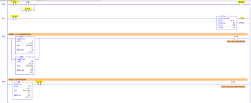
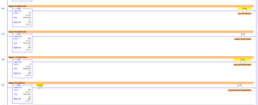
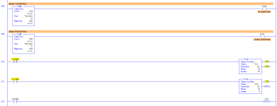
This is what I have so far.

I need to use the same flasher for the red lights when there is a power outage. Then when power restores the program needs to begin at Stage 1 again.

Any insight/opinion is greatly appreciated. Thank you!

TL1.png TL2.png TL3.png
 
Any insight/opinion is greatly appreciated. Thank you!

  • First of all: well done; you have grasped the core idea solidly
  • On RSLogix 5000, if that is where this ends up, 0.001s is the only time base; if not, wouldn't the 1.0s time base be easier to deal with?
  • Rung 002, several comments:
    • N/W Stop could be done with one LIMit instruction, cf. right-hand image on page 320 here.
    • Same for E/W Stop, Rung 009: use GEQ instead of LIM
    • There is an even simpler way to determine when Stop lights are on without any reference to the .ACC value, assuming the program already assigns the states of the Green AND Caution for that same direction; think about it.
      • The advantage to changing to this alternate control of STOP lights would be fewer limits to keep track of e.g. say if customer wanted to increase Caution durations by a few seconds, then there would be fewer numbers to change and fewer potential mistakes to be made.
      • The disadvantage of changing would be that Stop logic is of a different form than Advanced Green, Caution, and Green, logic, so readability suffers.
  • Values in the current LIM instructions need to be double checked e.g.
    • Stage 1 duration is 2s: .ACC will be 0 to 19 (or 0-1 for 1.0s time base, or 0-199 for 0.001s time base)
    • Stage 2 duration is 4s: .ACC will be 20 to 59 (or 2-5 or 200-599); compare to limits used in rungs 002 and 003
    • Stage 3 duration is 5s; .ACC will be 60 to 109 (or 6-10 or 600-1099); compare to limits used in rung 004
    • Stage 4 duration is 3s; .ACC will be 110 to 139 (or 11-13 or 1100-1399); compare to limits used in rung 005
    • Stage 5 duration is 2s; .ACC will be 140 to 159 (or 14-15 or 1400-1599); compare to limits used in rung 006
    • Stage 6 duration is 4s; .ACC will be 160 to 199 (or 16-19 or 1600-1999); compare to limits used in rung 007
    • Stage 7 duration is 4s; .ACC will be 200 to 239 (or 20-23 or 2000-2399); compare to limits used in rung 008
    • Stage 8 duration is 3s; .ACC will be 240 to 269 (or 24-26 or 2400-2699); rung 009 is okay as is.
      • Or simply [GEQ .ACC 240] (or [GEQ .ACC 24] or [GEQ .ACC 2400]); LIM is not needed
  • Comment on Rung 002 should start "Stages 1,2, 5-8 ..."
  • Comment on Rung 005 should start "Stages 1-6 ..."
  • Major style nitpick:
    • Where are the comments for the timing logic (Rungs 001 and 012)?
    • Where are the comments for Rung 000?
  • If B3:0/0 value is 1 when system running normally, e.g. without power failure, then perhaps an [XIC B3:0/0] should be ANDed (added in series) with each rung's logic feeding a light output.
    • Then a branch with [XIO B3:0/0] in series with flashing logic could be added to Stop sign rungs.
  • Minor style nitpick:
    • Rung 001, near the start of the program, has some of the 270ds timer logc,
    • BUT Rung ,012 near end of the program, has logic to make that same timer automatically repeat.
    • Those two should be next to each other, at one end or the other of the program, because they are related.
    • The principle is related to separation of concerns cf. here
      • Specifically, in the OP there was mention of a struggle to figure this out
      • However, by separating the timing logic from the stage logic, a simple, readable program was developed.
      • So putting all of the timing logic together will further enhance readability.
But you have the core of it and should be able to get things right in the lab.
 
Last edited:
I can't thank you enough for all of your valuable insight, drbitboy.

You have cleared up a lot of confusion I had at the beginning.

Edit: The settings for the LogixPro's timers are that by default. When I am on RS Logix 5000 the timers are set for an easier time.
 
Last edited:
This should be hammered into every graduate engineer before they are cut loose in industry. the amount of code i have seen that is very clever but totally impossible to understand is staggering.


I have posted this several times.
For any given homework assignment or task at work, you must consider these instructions as the customers specifications.
1. read the specifications several times.
2. write down your understanding of what you read in a step by step fashion.
3. review what you wrote down and see if it makes since, modify if necessary.
4. Get with the mechanical designer and discuss the project openly and honestly. When your opinions differ in regards to an operation, discuss it, don't ignore it.
there must be a reason for a difference of opinion. modify your instructions and i/o to accommodate the mechanical design if possible. Mechanical design may have to be changed due to plc programming limitations.
YOU BOTH MUST be in agreement on all points of operation before going to step 5. you may have to modify/rewrite step 2 and 3 based on the discussion.
5. step through your notes again this time, you are the one following the instructions. In other words, you are the plc. Write down on paper the events you are doing.
For example, turn on hydraulic motor 1, write down hydraulic motor 1 on. If a sensor is needed, write that down.
6. continue through the instructions. When you turn off the motor, mark a line thru it.
7. go through your instructions with all the sensors, motor aux. contacts, outputs documented. Modify if necessary.
8. repeat step 6 until no changes are made.
9. Try to group your data words into some organized fashion. The more programs you write, the more organized you become
10. write the plc program using your notes in a step by step manner.
10A Over half way through writing the program you WILL realize a different/better way of doing something you are almost done writing
(or a new spec will require it) and you will completely rewrite it
10B It WILL happen more than once.
Note: 10A and 10B added to list. thanks Aabeck, member plctalk.net forum


11. DOCUMENT EVERYTHING!!! You may remember things today, but in 5 years and hundreds of programs later, you won't
remember, especially at 2 am, so DOCUMENT EVERYTHING. use easy to understand tags and rung comments.
12. MAINTENANCE is your best friend and your worst enemy.
if you work with them and find out what they can do, write the program where they can trouble shoot the program. they will be able to fix the problem and everyone will be happy.
BUT
if you write the program to where you are the only one who understands what is going on, maintenance can't fix the issue, the machine is down, production is down,
management hears about it, your boss hears about it, then you hear about it - rewrite the program or else. you get calls all hours of the day and night.
this still holds true, a machine can cost a billion dollars, but it's not worth 10 cents if maintenance cannot trouble shoot the issue and fix the issue.
everyone has their own style of programming and you must develop your own way as well.
13. when the customer is in your shop and brings maintenance, discuss things with them, let them see your code, be open.
if they make suggestions, write them down, don't ignore them. their ideas may save you days of programming.
14. install the program and leave in program mode if possible so you can to debug your i/o
15. when writing your instruction manual(s), use your notes from step 9. Use easy to understand English language. specify the i/o, timers, counters, outputs when possible.
this will help maintenance even more to see what is going on.
16. Question for you, when is a machine and plc the most dangerous and why?
When it’s first powered on – when power is first applied to a machine, you don’t know how things are wired.
When you energize the plc outputs, you don’t know how they are wired.
When the plc is put into run mode the first time, it will do what you told it to do, NOT what you wanted it to do.


17. debug the program.
Remember, the program will always do what you told it to do, NOT what you wanted it to do.
18. IF you can ask a what if this happens type of question, YOU MUST have an answer, EVEN IF its a 1 in a million chance. that what if situation will happen in the first 30 minutes of production runoff in front of the customer.
regards,
james
 

Similar Topics

The idea here is to provide for a brief rapid influx of message codes while preventing sequentially repeating the same message. i.e. if two...
Replies
23
Views
694
Hi Group, I have a EZ-420 PLC and part of a program and I am trying to create a complete program for an E-Stop test bench. I have just...
Replies
9
Views
2,350
I'm having an issue with editing my Alarm settings within the Cimplicity workbench. I am attempting to change alarm sounds and settings dependent...
Replies
7
Views
4,330
I have a customer in Phoenix where we are starting up equipment. I will be out of town and cannot be there. The job has Siemens HMI, Siemens...
Replies
3
Views
2,011
Hello Guys, Well just a little back ground as to how the problem started. Last night our governors decided (somehow, we still don't know how yet)...
Replies
6
Views
1,634
Back
Top Bottom