Mitsubishi FX5 Strain Gauge Problems

Viv-V

Member
Join Date
Jul 2022
Location
Slovenia
Posts
4
Hello,

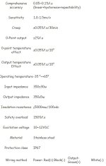
I'm currently working on a project where I need to read values off my 0-3kg Strain Gauge and display them on my HMI display.

I've connected the SG to a Mitsubishi A/D module per the V1+ input and COM, wrote a test program in GX-W3 and displayed the values to the HMI.

Problem is the values do not make sense. When I display them I get a 10 character number, where the last 8 digits change slightly upon detection of force. It also jumps erraticaly (not at all incrementaly) over the value 0 to -10 digit number, upon the reversal of force on the sensor. How could I fix this?

Other info:
-PLC: FX5UC-32MT/DSS-TS
-A/D: FX5-4AD-ADP
-SG is wired directly to the A/D, no external AMP
-The Strain Gauge was tested on an Oscilloscope prior to being connected to the PLC, and was working fine.
-A/D configured in GX-W3 to -10v - 10v range. I tried using the scale function, but with it turned on, the display did not work at all.
-GT-D3 used for the display, with Signed 32bit display option, reading from D10 register.
-Program and Strain Gauge info in attached pictures.

Thank you for the help

Program.jpg Strain.jpg
 
A strain gauge is typically supplied with a constant external voltage. What you will be measuring will be only millivolts. The sensitivity of your unit is quoted as 1.0 - 1.5mv/v. Therefore if you use a 10 volt supply, the maximum output from your loadcell fully loaded wil be 10-15 millivolts.
 
If you are using a conventional PLC analog input then you really need to get a loadcell amplifier to bring the strain gauge output up to a level for the PLC to read.
 
Where is the decimal point in the displayed number?

What are typical values in D0 and D10?

Can you give an example of a simultaneous set of the three displayed values of the measurement: D0; D10 (should be the same as D0, but floating point); what the HMI is displaying?
 
Last edited:
If you are using a conventional PLC analog input then you really need to get a loadcell amplifier to bring the strain gauge output up to a level for the PLC to read.

Yes I'm think you are right. Do you have any recomendations?
I was thinking of using a HX711 and maybe an Arduino to handle the aplification on a limited budget, since it's for my thesis.
 
Where is the decimal point in the displayed number?

What are typical values in D0 and D10?

Can you give an example of a simultaneous set of the three displayed values of the measurement: D0; D10 (should be the same as D0, but floating point); what the HMI is displaying?

I can't give you precise values for those since my lab is under maintenance until monday.

What I can tell you is, that the HMI gives vastly different results based on the type of display option selected. The ones that give me somewhat useful values are:
-Real (those values range from -8 to about +12; without any decimal points) and:
-Signed 32bit (10 digit values without any decimal points)

Reading measurements of D0 and D10 seemingly makes no difference (same result on HMI)
 
You need to incorporate the load cell amplifier as @Liam Moran says.

As to the 10-digit numbers, if

  • the raw values in D0 range from -16 to +16 (integers), and
  • you used INT2FLT to convert those values to -16.0 to +16.0 in D10,
  • but had the HMI read the bits (cf. item (i) below) in D10 as 32-bit signed integers
then your results make perfect sense; see here; the correlation ([D0],[D10 float bits displayed as integer]) probably looked like this:

$ python
Python 3.8.13...
>>>
>>> import struct
>>>
>>> for i in range(-16,17): print((i,struct.unpack('i',struct.pack('f',float(i)))[0],))
...
(-16, -1048576000)
(-15, -1049624576)
(-14, -1050673152)
(-13, -1051721728)
(-12, -1052770304)
(-11, -1053818880)
(-10, -1054867456)
(-9, -1055916032)
(-8, -1056964608)
(-7, -1059061760)
(-6, -1061158912)
(-5, -1063256064)
(-4, -1065353216)
(-3, -1069547520)
(-2, -1073741824)
(-1, -1082130432)
(0, 0)
(1, 1065353216)
(2, 1073741824)
(3, 1077936128)
(4, 1082130432)
(5, 1084227584)
(6, 1086324736)
(7, 1088421888)
(8, 1090519040)
(9, 1091567616)
(10, 1092616192)
(11, 1093664768)
(12, 1094713344)
(13, 1095761920)
(14, 1096810496)
(15, 1097859072)
(16, 1098907648)


It's all about the bits.
 
Last edited:
You need to incorporate the load cell amplifier as @Liam Moran says.

As to the 10-digit numbers, if

  • the raw values in D0 range from -16 to +16 (integers), and
  • you used INT2FLT to convert those values to -16.0 to +16.0 in D10,
  • but had the HMI read the bits (cf. item (i) below) in D10 as 32-bit signed integers
then your results make perfect sense; see here; the correlation ([D0],[D10 float bits displayed as integer]) probably looked like this:

$ python
Python 3.8.13...
>>>
>>> import struct
>>>
>>> for i in range(-16,17): print((i,struct.unpack('i',struct.pack('f',float(i)))[0],))
...
(-16, -1048576000)
(-15, -1049624576)
(-14, -1050673152)
(-13, -1051721728)
(-12, -1052770304)
(-11, -1053818880)
(-10, -1054867456)
(-9, -1055916032)
(-8, -1056964608)
(-7, -1059061760)
(-6, -1061158912)
(-5, -1063256064)
(-4, -1065353216)
(-3, -1069547520)
(-2, -1073741824)
(-1, -1082130432)
(0, 0)
(1, 1065353216)
(2, 1073741824)
(3, 1077936128)
(4, 1082130432)
(5, 1084227584)
(6, 1086324736)
(7, 1088421888)
(8, 1090519040)
(9, 1091567616)
(10, 1092616192)
(11, 1093664768)
(12, 1094713344)
(13, 1095761920)
(14, 1096810496)
(15, 1097859072)
(16, 1098907648)


It's all about the bits.

You are absolutely. Now that I read your explanation it makes perfect sense. Seems like I missed the forest for the trees. Thank you for the great reply!

I definitely need to search for a suitable aplifier now...
 
the maximum output from your loadcell fully loaded will be 10-15 millivolts.
With a signal range of ±10mV, and with the FX5-4AD-ADP resolution of 0.625mV/count, there would not be a reading that would place a value into D0 (integer) of beyond a couple dozen counts, which is in the ballpark of the -8 to +12 displayed when D10 is interpreted by the HMI as a REAL.


You could always apply a voltage of around 10kV to avoid the amplifier ;).
 
Seems like I missed the forest for the trees.

Meh. I always think about the bits first, so it's easy for me; as soon as I saw the INT2FLT instruction I knew what happened. At least you understand.

"It's only ones and zeros; it cannot be hard" - Jouni Ryno
 

Similar Topics

I’m fairly new to PLC programming. This is our first machine that uses an FX5 PLC rather than an FX3, and therefore GX Works3 instead of GX...
Replies
1
Views
1,256
Hi, Today, i got another new task. its Mitsubishi now. I don't know how to handle this. when I try to download an HMI screen, which has many data...
Replies
1
Views
1,096
Hi, I am trying to create a program for the 5U that can communicate to 2 or 3 VFDs (individual control, not broadcast) using the inverter...
Replies
0
Views
1,032
Hi all, I would really appreciate any help with the FX5 PLCs in regards to the issues mentioned below. Not too sure whether this is important...
Replies
4
Views
2,009
Hello everyone! I am the beginner with PLC's. I have a plc mitsubishi fx5, and i want to control inverter by built-in analog in that plc. I set up...
Replies
2
Views
2,394
Back
Top Bottom