TOMENGLAND
Member

Hello Team, I am desperate for some help with an assessment I have as part of a Level 3 general engineering course. I am in a role that is much more mechanically based so struggling with this PLC segment and wondered if someone could help me.
The question is as follows:
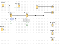
The application above illustrates a simple stirring application in a lemonade factory.
Use LOGO to design and build the above system, using function block or ladder logic, which will control the operation as follows:
When the Start ‘push to make’ (not toggle) switch (I1) is pressed/released, and gets latched on (B1: RS latch), the start ‘fill’ pump (Q1) will be energized and the tank will start to fill.
The pulses generated by flow meter 1 (B5: pulse generator) should be used to increment the counter (B6: Up/down). Tank level full is when the counter function on = 10 and tank low level is when counter off = 1. These values can be used as feedback to control the pumps (instead of the high/low level sensors shown above) and can be called the ‘tank high/low level count indicator’ (Q5 or use a flag M1)
When the full liquid level in the tank is sensed by the tank high/low level count indicator (Q5), the fill pump will be shut-off and the FULL light (Q2) on the control panel is to be energized.
When the tank is full, start the mixer (Q3) and run for 10 seconds (B8: off-delay timer).
When the 10 seconds has expired, stop the mixer (Q3) and start ‘empty’ pump P3 (Q4).
Pump 3 (Q4) will be required to run until the tank is empty.
The pulses generated by flow meter 3 (B15) should be used to decrement the counter (B6: Up/down). Tank empty can be detected by the high/low level count indicator (Q5 or use a flag M1) to switch off the pump
When the stop button (I2) is operated, the process must stop immediately (Q1, Q3, Q4).
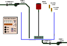
Test your LOGO build and comment on your testing using LOGO simulation mode. This requires at least 3 print-screens of testing the system using the LOGO simulator below at the filling, mixing and emptying stages. Clearly snip/print-screen and explain your build and test work. Use input/output (I/Q) numbers shown. Function numbers (B) can be your own choice, and you are also likely to need some basic logic functions (e.g. And/Or/Not) for the various conditions given in 3a.
Any help would be massively appreciated as I am so stuck on where to go with this, if anyone can help with screenshots, files etc. if needed I can provide my email through private message.
Thank you
The question is as follows:
The application above illustrates a simple stirring application in a lemonade factory.
Use LOGO to design and build the above system, using function block or ladder logic, which will control the operation as follows:
When the Start ‘push to make’ (not toggle) switch (I1) is pressed/released, and gets latched on (B1: RS latch), the start ‘fill’ pump (Q1) will be energized and the tank will start to fill.
The pulses generated by flow meter 1 (B5: pulse generator) should be used to increment the counter (B6: Up/down). Tank level full is when the counter function on = 10 and tank low level is when counter off = 1. These values can be used as feedback to control the pumps (instead of the high/low level sensors shown above) and can be called the ‘tank high/low level count indicator’ (Q5 or use a flag M1)
When the full liquid level in the tank is sensed by the tank high/low level count indicator (Q5), the fill pump will be shut-off and the FULL light (Q2) on the control panel is to be energized.
When the tank is full, start the mixer (Q3) and run for 10 seconds (B8: off-delay timer).
When the 10 seconds has expired, stop the mixer (Q3) and start ‘empty’ pump P3 (Q4).
Pump 3 (Q4) will be required to run until the tank is empty.
The pulses generated by flow meter 3 (B15) should be used to decrement the counter (B6: Up/down). Tank empty can be detected by the high/low level count indicator (Q5 or use a flag M1) to switch off the pump
When the stop button (I2) is operated, the process must stop immediately (Q1, Q3, Q4).
Test your LOGO build and comment on your testing using LOGO simulation mode. This requires at least 3 print-screens of testing the system using the LOGO simulator below at the filling, mixing and emptying stages. Clearly snip/print-screen and explain your build and test work. Use input/output (I/Q) numbers shown. Function numbers (B) can be your own choice, and you are also likely to need some basic logic functions (e.g. And/Or/Not) for the various conditions given in 3a.
Any help would be massively appreciated as I am so stuck on where to go with this, if anyone can help with screenshots, files etc. if needed I can provide my email through private message.
Thank you

") ) try to not do the work for students. Because someday in the future we or someone might be in a plant where those former students, having passed the course or gained certification, have programmed the logic for dangerous equipment, and we would prefer the comfort of knowing they actually understood what they were doing. There is no ethical shortcut to learning.
) try to not do the work for students. Because someday in the future we or someone might be in a plant where those former students, having passed the course or gained certification, have programmed the logic for dangerous equipment, and we would prefer the comfort of knowing they actually understood what they were doing. There is no ethical shortcut to learning.