VSD with safe torque off and two phase mechanical brake

ASF

Lifetime Supporting Member
Join Date
Jun 2012
Location
Australia
Posts
3,921
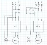
We have an existing VSD where a three phase circuit breaker feeds the drive, and two phases also tee off to a contactor, which is energised to release the brake.

Currently if a safety circuit is tripped, redundant safety contactors remove the three phase supply, which (a) removes power from the VSD, and (b) removes power from the brake. This means that under emergency stop conditions, the motor is stopped and the brake is engaged. This is important as the load is a high inertia load with lots of sharp things on it.

The VSD is now being changed from a powerflex 40 on DeviceNet, to a Powerflex 525 on Ethernet. Removing power from the drive due to emergency stop is not desired due to (a) shortening the lifespan of the drive, and (b) a loss of communication every time this occurs (exacerbated because this replacement covers ~20 drives in a DLR loop across multiple safety zones

So, we will make the three phase supply to the drive non-isolated, and use safe torque off. However, the supply to the brake still needs to be isolated by safety contactors under emergency stop conditions, to ensure that the brake engages on e/stop.

My concern is that currently, one circuit breaker removes power to all motor wiring (windings via VSD, and brake via contactor), but if I can't tee the brake off the drive circuit breaker any more, I'll need a separate circuit breaker for the brake, and there's no longer a single isolation point for that motor.

How do you folks handle this? Do five-pole breakers exist somewhere? Do linking kits exist so that I could mechanically link a three pole breaker with a two pole breaker mounted next to it? The motor itself has a six-pole isolator (three phases, brake, and PLC feedback), but I don't know what to do at the MCC side.
 
Last edited:
So you currently have the incoming supply go in parallel to the VFD circuit breaker and to the brake circuit breaker?

Can't you feed the brake circuit breaker off of the secondary of the VFD circuit breaker? Then the VFD circuit breaker locks out everything. How big is the motor and brake?
 
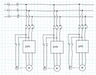
It's like the one on the left, except that the safety contactors are upstream of the circuit breaker, because they're common to all motors. And the brake has a separate (non-safety) contactor for control. Since the safety contactors are common we can't rearrange it as per the right drawing
 
Yes, that's exactly what we have now. And we need to move the drives supply prior to the safety contactors, but leave the brake supply downstream of the safety contactors. Of course, we can just put a separate two-pole breaker in for the brakes, but that just means we no longer have a single point of isolation at the MCC to isolate all conductors to the motor. Unless I can find a five-pole breaker, or a mechanical link to force a 3-pole and 2-pole breaker to operate together.

@JesperMP yes there is a 6-pole "repair switch" (we call them local isolators here) between the drive and the motor, that part is fine. It's just that, currently, there's a single isolation point at the MCC to isolate all conductors to the motor, and if we have to split them, that won't be the case any more.
 
What is the purpose of the 'single isolation point' in the cabinet ?

A main switch in a control cabinet isloates the entire cabinet so that you can do electrical work in the cabinet.A repair switch is intended to provide isolation for repair and maintenance on a machine or a machine part.
A local repair switch near the machine part it isolates is better than an isolator that is placed far away from the machine part.


edit: The only purpose I can imagine is if you need to do cable work from the cabinet to the repair switch, all the while the cabinet is powered up.
In that case it is a job for an electrician, and he must certainly be able to identify where to isolate the cables. And the electricaian should follow LOTOTO procedure. It really doesnt matter if the cables go to the same location (i.e. a single motor) or not.
 
Last edited:
Yeah it's not a show stopper by any stretch, it's just a case of "currently there's only one circuit breaker involved, and when we're done there will be two". If this were a new install I'd be less concerned, but as I'm making an existing system less simple, I wondered if anyone has come across this and found a neat way of integrating it. It's only one cable to the motor, so if I could find a solution that isolates all those conductors with one isolation point that just means I'm not adding any additional complexity.
 
You could use a safety contactor for the brake solenoid controlled by the vfd output in series with an output of the safety relay. That way either point will drop out contactor and engage the brake while still utilizing the same CB.
 
So, the breakers are currently protecting the drives and the brakes, right? I would be surprised if the breaker sized to protect the drive is suitable to also protect the brake, but that's a different issue. It can certainly protect properly sized wires feeding both.
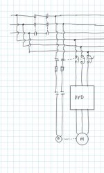
Can you add fuses to protect the brakes and use aux contacts on the breakers so there's a single isolation point? The safety contactors still isolate the brakes but not the power feeds to the drives. Aux contacts on the CB provide an isolation point that removes power from the drive and brake at the same time. Fuses protect the brake and its wiring.

VFD-Brake3.JPG
 
I might be nit-picking here. And I still do not know what is the purpose of the isolation function.
But if the purpose is for removal of energy before doing maintenance on dangerous parts - that be electrical or mechanical, then safety devices such as E-stops and safety relays and contactors are not supposed to be used as the isolation devices.
The isolation device in such a context is usually hand-operated, works directly on the energy source, and possible to lock with a personal pad-lock.
At least that is the code in the EU. Don't know about Australia.
 
Last edited:
So, the breakers are currently protecting the drives and the brakes, right?
Correct.

I would be surprised if the breaker sized to protect the drive is suitable to also protect the brake, but that's a different issue. It can certainly protect properly sized wires feeding both.
These are all quite small motors, so the breaker is fine to protect both VSD and brake. The VSD protects the motor. On larger motors with this architecture, we typically use a second breaker downstream of the main breaker. That way the main breaker still acts as a single isolation point, but the secondary breaker provides short circuit/overcurrent protection for the brake.


Can you add fuses to protect the brakes and use aux contacts on the breakers so there's a single isolation point?
We could, but a circuit breaker auxiliary is not reliable as an isolation point. It can fall off the side of the breaker and not operate when the breaker is switched off.

I might be nit-picking here. And I still do not know what is the purpose of the isolation function.
But if the purpose is for removal of energy before doing maintenance on dangerous parts - that be electrical or mechanical, then safety devices such as E-stops and safety relays and contactors are not supposed to be used as the isolation devices.
The isolation device in such a context is usually hand-operated, works directly on the energy source, and possible to lock with a personal pad-lock.
At least that is the code in the EU. Don't know about Australia.
Pretty much the same here. The safety relays/safety contactors are not for isolation purposes, they're for safety purposes. We need to be 100% confident that if we hit an emergency stop, no only will power be removed from the motor (drive STO) but also that power will be removed from the brake (i.e. brake engaged) so that the spinning blades stop as fast as possible. That part of it is relatively straightforward. The question of isolation is a secondary concern, and by the looks of it we're just going to have to have separate isolation points for the VSD/motor and the brake (as mentioned previously, there is also the local isolator that is a single point of isolation for all other isolation purposes). That's acceptable, it's just slightly less neat than I'd like, especially given that we're changing an existing system, and I prefer not to make things more complicated when making modifications if I can avoid it. In this case there's no choice because the safety architecture takes precedence over convenience, and things like 5-pole breakers or mechanical breaker linking kits don't appear to exist/be readily available.
 

Similar Topics

Hi hoping someone can assist me with current issue I am experiencing with an ABB drive. Problem I’m experiencing is a ABB drive supply a large...
Replies
4
Views
210
Hi all, We have an fr a740 inverter that is displaying a warning on the fr pu04 operator panel. Everything seem to be fine with the inverter but...
Replies
5
Views
1,417
Hi, New to this so please bear with me. I have this controlling a Netzsch Progressive cavity pump at 30Hz and the pumps motor is rated at 21A...
Replies
6
Views
3,225
Hello All, Not exactly a PLC question but more looking for advice on a PROFIBUS controlled ABB ACQ810 VSD. The drive is controlled over the...
Replies
1
Views
1,033
Hello All, Not exactly a PLC question but more looking for advice on a PROFIBUS controlled ABB ACQ810 VSD. The drive is controlled over the...
Replies
1
Views
1,123
Back
Top Bottom