Urgent need of help in Vijeo Citect 7.4

Aimin Ariff

Member
Join Date
Mar 2023
Location
Selangor
Posts
28
I have DI module ICPCon M7024UD connect to my pc using COM3 MODBUS RTU and also RHT sensors are using MODBUS TCPIP.. The problem is, it cannot read the DI module values.. It wrote bad.. Here are the pictures of the settings.. please help me guys, please.. I dont know what to do anymore.. Or is there steps to reconfigure Communication Express Wizard?

anydesk00071.png
 
You have configured board name as "Board1"
On Board coonfiguration you should have "Board1" instead of "Board2" also probably board type OFS is wrong, it should be Com3?
Also port number is probably wrong. Try 1 if com3 is defined on elsewhere.

Allready years when have configured citect so not remenber all anymore.


Look at this diagram setup of configuration for serial.
https://johnwiltshire.com/citect-help/Content/Configure_IO_Device_Communications.html


p.s It should be

Board name: Board1, board type Comx, channel 0.


on ports:
Port number 3 = Com3.
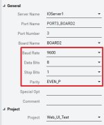
baud, data, stop bits as on IO device.

Board name = Board1 so Citect can see right port.
Port name = port1.


I/O devices config (port1)
Slave number there
 
Last edited:
I have changed everything but right now. If I am using communication express wizard to add new device with new MODBUS Protocol which is Industry Standard Protocol using MODBUS RTU, it didnt create anything.. Please help me.. Device communication Wizard seems lock and cannot create anything
 
When using modus rtu, board type will be "comx" on the ports form port number will be the comm port number and baud rate etc. Can't post screenshots but the driver help is generally pretty good.
 
Okay, I have setup everything. COM port, COMX and setup the device unit.. But apparently the data wrote #BAD.. Hmm.. What could possibly go wrong
 
I have set everything.. But I cannot set using Communication Express Wizard.. Should I try MODBUS10 or any other drivers?

For clear other errors from system I recommend

1. Use PC test direct with device by Modbus Software like ModbusPoll or RMMS first. If you do not have software use this link below.

https://en.radzio.dxp.pl/modbus-master-simulator/

2. Test on Starter Project. Stop work on your project now and create new (include select starter project) for test and use Communication Setup Wizard to create modbus device after finish them change parameter on "Ports" Section to match with device parameter and test project
 
For start to add modbus device in easy way by Communication Setup Wizard

1. You need to have serial port on ypur PC first if it is USB or Lan converter to Rs-485 please attach and install driver first

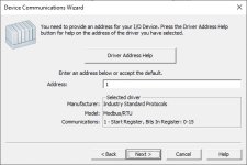
2. On Citect start Device Communication Wizard

3. Select current project

4. Select IOServer that you use

5. Create your Modbus Device Name

6. Select External I/O Device

7. Selcet Driver to -> Industry Standard Protocol -> Modbus/RTU -> 1 - Start Register, Bit in registers 0 - 15 (Can be change later)

attachment.php


Then click next

8. Input Modbus ID of your device here (Can be change later)

attachment.php


9. Next until page detect serial port -> select port that connect with device

attachment.php


10. Click next until finish

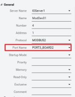
11. Go to I/O Device and find your Modbus device name that you create and find which port_board that been used. (You can channe Modbus ID / Address here.)

attachment.php


12. Go to Ports and select that port. You will be find communication parameter change them to match with your device

attachment.php


13. Create some modbus device and test to run
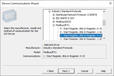
Citect_Modbus_Device_Setting_004.jpg Citect_Modbus_Device_Setting_005.jpg Citect_Modbus_Device_Setting_007.jpg Citect_Modbus_Device_Setting_010.jpg Citect_Modbus_Device_Setting_011.jpg
 
Thanks a lot guys.. I have MODBUS RTU driver installed and I also follow the details steps you have given me WASAN and thank you for that! It turns out the problem is that the port cannot have same name of board.. Eventhough the name is different which are, board1 and BOARD1, it cannot read it although the diff is capital letter.. Then, the IO devices cannot be created to to corrupted OID file, so it does not generate.. Thanks again guys
 

Similar Topics

HMI (MT506TV) died on legacy machine in our plant. We have some SW back up and we have found another panel in spares, but i dont have software...
Replies
2
Views
1,659
Hey Guys and Gals Our paint shop has a 1784 plc 5/25, Last week we had a power outage, followed by several surges. Of course, we got the paint...
Replies
24
Views
4,844
Dears, Kindly I have a problem and need your urgent help, I am trying to upload/ read back the program of my Lauer PCS900 operating panel, through...
Replies
1
Views
1,839
Hi all, Its been a long time since the last time I visit this site. Actually I changed my career to something close to electronics but a little...
Replies
7
Views
2,453
Hi all, I'm desperately trying to upgrade all our factory PLCs to S5. We used to have S7 PLCs (mostly 315 PN/DP) but we were finding them...
Replies
9
Views
2,662
Back
Top Bottom