Guidance on upgrade of vintage timer/relay to new digital style

JoeM61

Member
Join Date
Jan 2024
Location
trenton
Posts
26
Question to anyone with ideas about my thoughts on upgrading a very vintage timer, which is being used to switch between 2 5hp domestic water booster pumps for maintaining system pressure in 10 story building. Every 24 hours the pumps switch between duty. There is no lead or lag built into the system and as far as I can tell the Mercroid high pressure limit switches have never been tripped (pressure being made) They just run 24/7 year in and year out.
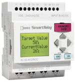
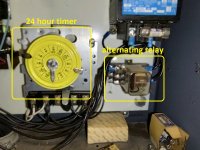
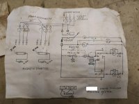
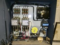
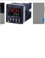
I've attached the schematic, a picture of the components and a picture of the timer and alternating relay. I also attached a pic of the type of timer/relay that I believe could replace this older system. I like the idea of mounting the digital timer through the front panel door. Any thoughts on wiring, potential issues, confirmation or best recommendations for this simple task...simple I'm guessing from the view point of the average contributer to this site anyway.
thanks,
 

Attachments

  • 24timerwheelRelay.jpg
    24timerwheelRelay.jpg
    233.4 KB · Views: 50
  • TWdualboasterpumpschem.jpg
    TWdualboasterpumpschem.jpg
    207 KB · Views: 48
  • TWcontrolbox layout.jpg
    TWcontrolbox layout.jpg
    131.7 KB · Views: 49
This would be a pic of the type of timer that I think should be a good substitute (?)
 

Attachments

  • TWnewTimer.png
    TWnewTimer.png
    280.2 KB · Views: 14
The original is a timeclock rather than a timer as in the picture in your second post, timeclocks are used a lot on home heating systems, so you should be able to get a cheap device. The only other thing that might be an issue is the relay coil rating, to cover that off make sure you send it a short changeover pulse.
 
Thanks Bryan, do you mean the relay coil rating in the new timer? Could you expand on your comment about making sure to send a short changeover pulse?
Thanks
Joe
 
Why fix it, if it is not broken?
Are replacement parts still available?
I have seen a lot of those time of day timers used for water heaters and pool pumps, so I know they are still made.
Not sure about the flip/flop relay, but you could use a standard relay with one NO, and one NC contact. The current design is easy to troubleshoot and maintain. Not sure the replacement would be as user friendly.
 
Hi, I mean the coil in the existing relay, it changes over when it gets a pulse from the timeclock/timeswitch. That type of relay doesn't always have a coil that is good for 100% duty, so if you put power on the coil for too long, it can get too hot and burns out. The only way to know would be to get the part number and find a datasheet. It was just something to be aware of. I can't advise on specific a timeclock/timeswitch for you to get, things are different on this side of the Atlantic :)
 
Why fix it, if it is not broken?
Are replacement parts still available?
I have seen a lot of those time of day timers used for water heaters and pool pumps, so I know they are still made.
Not sure about the flip/flop relay, but you could use a standard relay with one NO, and one NC contact. The current design is easy to troubleshoot and maintain. Not sure the replacement would be as user friendly.
Thanks, It is broken. The alternating relay no longer switches per the 24 hour design so only one pump runs continually. I should be able to do a cheap alternating relay swap out but I wonder if for a few dollars more a single device ie time clock and switching relay with a fancy digital read out mounted through the front door panel might be a viable upgrade(?) With the led timer displayed, one could walk by during a routine inspection and see the timer working and which pump is running without having to shut water down on a 10 story building just to open the enclosure for a routine monthly inspection (?) Are these timer units durable enough for this idea?
 
Hi, I mean the coil in the existing relay, it changes over when it gets a pulse from the timeclock/timeswitch. That type of relay doesn't always have a coil that is good for 100% duty, so if you put power on the coil for too long, it can get too hot and burns out. The only way to know would be to get the part number and find a datasheet. It was just something to be aware of. I can't advise on specific a timeclock/timeswitch for you to get, things are different on this side of the Atlantic :)
Thank you! That's exactly what I'm asking. Can these types of digital timer / alternating relays handle the existing mechanical based design already in place ? If so the benefit would be that one could walk by visualy observe it working through the display. The existing design requires the building be shut down in order to open the control box and do a monthly PM inspection.
 
Why fix it, if it is not broken?
Are replacement parts still available?
I have seen a lot of those time of day timers used for water heaters and pool pumps, so I know they are still made.
Not sure about the flip/flop relay, but you could use a standard relay with one NO, and one NC contact. The current design is easy to troubleshoot and maintain. Not sure the replacement would be as user friendly.
Btw thank you for the "user friendly" mind set.. I feel that sometimes institutions spend good money on systems that no one understands or can troubleshoot. What is there is pretty simple and has worked for years.
 
I don't know if it the same in the US, but we generally have a 'you touch it, you own it' system. Also if you start changing things, does it have to be approved. Looking at your picture, pretty much everything in there is IP absolutely zero, not finger safe, not slightly, designed to kill people, wouldn't touch it with a barge pole (do you have barge poles in the US? :) ) Would at least want a large piece of perspex between me and it.
Why fix it, if it is not broken?
Yeah, but I would take a different view, I would have used that clock and relay 20 years ago, but now it would be a door mounted smart relay. The screen would show which pump was running, how long each pump had run, and how long sleeping, when a pump was last serviced, maybe the voltage coming in to the box, and maybe even when the power last went out. If I could log the water temperature and pressure, happy days. And if the relay has an Ethernet port it would be on a LAN and I would be able to remote access the data.
The easy life is to do a like for like replacement, but the easy life doesn't stop you having to shut the building down once a month.
 

Attachments

  • Smart relay.png
    Smart relay.png
    81.5 KB · Views: 2
I like this "different view" forget the digital timer/relay and pay a little more for a plc or smart relay who's inputs and outputs can be build out over time. Just program the 2 pumps to alternate via a software timer and even build out overload protection features better than what's there now.. in fact the current overload feature (other than current overload) is an aquastat that detects water temp rising to disrupt the pumps.. pretty sure that stopped working years ago. In the case of using a PLC I feel like a brand wiht supporting free program software and that operates on 120v (delivering 120v to motor contactors via onboard plc relay) would be the best choice (?)
 
What is easily available here is different from the US, so I can't give specific recommendations. I had a quick look and PLCs and smart relays with 120V supply and 120V inputs do seem to be available. I don't know if all the smart relays allow you to put messages on the screen, I know that the Moeller (now Eaton) ones that I used to use did. You can put the smart relay behind a window like this:
Or you can go for a PLC with a separate HMI, more expensive but more flexible. Again choice of device has to be set by what is available in your market.
 
Looking at the pin layout on that timer/relay and applying it to the wiring schematic attached would any non-busy / semi retired pros that like to keep sharp offer suggestions of which way to wire this up so as to be able to remove the clock and the relay also attached in the pic?
I have a general idea but low confidence whether warranted or not.
thanks.
 

Attachments

  • TWdualboasterpumpschem.jpg
    TWdualboasterpumpschem.jpg
    207 KB · Views: 10
  • TWcontrolbox layout.jpg
    TWcontrolbox layout.jpg
    131.7 KB · Views: 10
  • timerrelay1.png
    timerrelay1.png
    165.2 KB · Views: 8

Similar Topics

I've got this 3-phase 575V motor that we're controlling with a VFD (Variable Frequency Drive), which has been quite the learning curve in itself...
Replies
10
Views
211
Hello All, We have assembly line and our supplier building automated line on top of it we are interfacing mes system. Our automation supplier...
Replies
0
Views
285
Hi all, I am getting back to using IEC for schematics and was wondering about the 81346-2:2019 codes. What does everyone use for a diffuse...
Replies
3
Views
559
So, if I had about $2K to spend on a new, 15” notebook PC with Intel brains and Win10 Pro, which hardware would you pick? I’m thinking 16MB RAM...
Replies
19
Views
7,049
As mentioned in the title, I want to learn about PLC systems. Long story short: I had to strip out a plant room. Everything was going to the...
Replies
9
Views
2,606
Back
Top Bottom