Configuring m221 and wecon HMI modbus RTU

hadwll

Member
Join Date
Oct 2017
Location
UK
Posts
21
disclaimer- 1,no one in their right mind would pick this configuration but I want to try and get it working. 2, my MB knowledge is sketchy at best.


I have the PLC setup as a master and the hmi as slave.


There are 3 blocks in the software, read_var, write_var and write_read_var


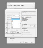
I want to press a button on the HMI and have that set a bit in the PLC, which function code should I use? (snip1)


attachment.php


I am assuming that I will want to write data so that would be FC 5 or 15. Lets go with 5 for a single coil..


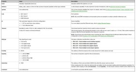
when I do that i set up the block to read the variable in the PLC as so (snip2)


attachment.php


objtype- 1 for digital input
firstobj as 20 as it was addresed at 20 in the hmi software ( have also tried 19)

quantity- 1 as it is 1 bit
index data- 5 (%mw5, just a home for it)


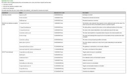
The error being returned is bad length (snip3)

attachment.php


I am thinking I am putting a bit into a word.. so that should be ok?


Where am I going wrong?


Cheers!


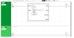
snip4 plc prg
attachment.php


snip1.png snip2.JPG snip3.JPG snip4.JPG
 
Is there reason why you want HMI to be slave and PLC master?


Usually HMI is master and much more easy to communicate as PLC don't need any blocks for coms.
If you another slaves, then you can connect panel with erhernet if you don't have two serials on PLC side.
 
Since both the PLC and HMI can be configured as either a master or a slave, first make sure that you actually have the PLC configured to be the Modbus master and the HMI configured to be the Modbus slave.

If the HMI is indeed the slave, you don't want to write data to it from your PLC. Your PLC needs to read from the HMI in order to get the current state of the button. The button state should be mapped to a digital input (Modbus Input Status) on the HMI. The PLC should use Modbus Function Code 2 and request 1 for the quantity.

I recommend using the divide and conquer method on this issue. Download both ModScan and ModSim. Use ModScan and connect your computer to the HMI. Confirm that you can read a single Input Status and see the state of the button change in ModScan. Next use ModSim and connect your computer to the PLC. Create one Input Status in ModSim and confirm your PLC can read it.


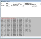
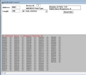
Thanks for the reply, I have been using modsim with some sucess I can use it to turn a light on the HMI (HMI set to master), however in modscan I am getting a checksum error and the device fails to connect.


attachment.php


when hmi set to master I get a timeout error.


attachment.php


I have checked, double and triple the communication settings. reduced the baud rate but to no avail


There are numerous slave settings in the HMI menu I have tried them all.


I feel like modbus is THE basic communication protocol for automation engineers. It would be nice to get a handle on it!

snip5.JPG snip6.JPG
 
Is there reason why you want HMI to be slave and PLC master?


Usually HMI is master and much more easy to communicate as PLC don't need any blocks for coms.
If you another slaves, then you can connect panel with erhernet if you don't have two serials on PLC side.


Thanks for the reply, I would consider this for sure if it works!
 
I think you may be a little confused on the master and slave roles. Keep in mind that ModScan is a Modbus master, while ModSim is a Modbus slave. You cannot have a master communicate with another master, nor can you have a slave communicate with another slave. You must have 1 master and 1 (or more) slave(s).

The point of the divide and conquer troubleshooting is to leave your equipment in the exact configuration that you will be using it in your application. You stated that you want the PLC to be the Modbus master and the HMI to be the Modbus slave.

Therefore, here are the two separate tests you should perform.

Test 1 - ModScan with HMI
The HMI should be configured as a Modbus slave. You will use ModScan to read one input status (digital input) from the HMI. In ModScan, you need to select "02: Input Status" for the MODBUS Point Type, set the Address to the address you mapped the digital input to in your HMI (20, I believe you said previously), and set the Length to 1. Note that because ModScan uses 1-based register addressing, if your HMI uses 0-based register addressing, you will need to enter 21 in ModScan's Address field.

Test 2 - ModSim with PLC
The PLC should be configured as a Modbus master. You will use ModSim to create one input status. In ModSim, you need to select "02: Input Status" for the MODBUS Point Type, set the Address to 21, and set the Length to 1. Note that the ModSim uses 1-based register addressing and your PLC appears to use 0-based addressing, so ModSim's Address field must be one more than your PLC's (i.e. if ModSim's Address is 21, your PLC must target address 20).
 

Similar Topics

Hello all and happy Friday, I'm curious if anyone here has experience sending data over an Anybus Bolt II (HMS AWB6001-A) using a Compact Logix...
Replies
4
Views
763
Hello everyone, I am looking for an easier way to configure all my IO for an OPTO22 PLC. I am developing in Codesys I have a GRV-EPIC-PR1 with a...
Replies
0
Views
583
Greetings to all. We have SST-SR4-CLX-RLL (Molex Modbus module) in remote backplane. The remote backplane, containing SST-SR4-CLX-RLL module, is...
Replies
0
Views
650
When configuring redundant ethernet cards, will the mac address change along with the IP address. A friend is having problems with IP security...
Replies
3
Views
1,250
I am working with an Emerson CPL410 PLC that is connected to a Siemens AI 8xU/I/RTD/TC ST (6ES7531-7K00-0AB0) via Profinet (and a Siemens Scanner...
Replies
2
Views
1,534
Back
Top Bottom