plc ladder

edwinda

Member
Join Date
Mar 2023
Location
jakarta
Posts
4
hi..i'm just learning plc. can anyone help me to plc landder with the command below like this:
• PB 1 is pressed GL will light up
• PB 1 is released GL remains on
• PB 2 is pressed RL will light up
• PB 2 is released RL will go out
• If PB 1 is not pressed first, PB 2 will not function and the RL lamp will not light up
• PB 3 is pressed, the GL lamp will turn off as well as the RL lamp
Symbol used
• PB1 (X0)
• PB2 (X1)
• PB3 (X2)
• GL (Y0)
• RL (Y1)
Thank You
 
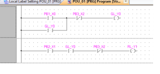
Simple, however, your logic does not make complete sense, if both buttons are press to turn on & release for off (I.E. momentary) then PB2 would have to be pushed in for the output to stay on and held on. the alternative is to use latches but this could only be done on button 2 in reality.
here is some logic but bear in mind that if any of the buttons are effectively stay put switches then you would need to use oneshot logic to latch/de-latch the outputs.

Logic.png
 
Simple, however, your logic does not make complete sense, if both buttons are press to turn on & release for off (I.E. momentary) then PB2 would have to be pushed in for the output to stay on and held on. the alternative is to use latches but this could only be done on button 2 in reality.
here is some logic but bear in mind that if any of the buttons are effectively stay put switches then you would need to use oneshot logic to latch/de-latch the outputs.

Thank you for the help. i really appreciate. wish you more success
 
Post a screenshot of your code & explaing or post a pic of the error
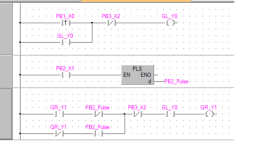
here is a modified one where they are both push to turn on push again to turn off for GR.

Logic1.png
 
you have wrong outputs your original wanted Y0 & Y1 then in your screen shots you are using Y20 & Y21 but the latch in cotacts are Y2 ? is this correct, you only mention Y0 & Y 1 in your original, you need a Y20 in Rung 4 so when Y20 (PL1) is off Y21 also goes off.
 
See this link: http://www.contactandcoil.com/patterns-of-ladder-logic-programming/


Read them in this order: Input Map pattern; Seal-in pattern; Start/Stop Circuit pattern; State Coil/Fault Coil pattern.

The point of reading the Input Map pattern is to understand the basic pattern is "If the input logic evaluates to True, then assign a 1 to the output element; if the input logic evaluates to False


The points of the Seal-in pattern are to understand that

  • two elements in parallel implement (encapsulate) a logical OR;
    • the result of two instructions ORed in the Seal-in pattern reduce to the "input logic" of the Input Map pattern.
  • digital PLCs evaluate logic in time, and understanding the that the scan cycle (usually) operates on a snapshot of the process in time. So read value of the seal-in tag in the XIC/Normally Open contact (usually) represents what the value of that tag was at the time of the end of the previous scan cycle, and the assigned value of the seal-in tag in the OTE/Output coil represents what the value will be at the time of the end of the current scan cycle.
The point of the Start/Stop Circuit and State Coil/Fault Coil Circuit patterns is to understand that

  • two elements in series implement (encapsulate) a logical AND;
    • the result of three instructions ORed and ANDed in the Start/Stop Circuit or State Coil/Fault Coil Circuit pattern reduce to the "input logic" of the Input Map pattern.
Getting back the original query, and ignoring the GL/RL interaction, two Start/Stop Circuit Patterns are needed:

  • One Start/Stop Circuit pattern for GL:
    • PB 1 is the tag of the Start element
    • PB 3 is the tag of the Stop element
    • GL is the tag of the Run and Seal-in elements
  • One Start/Stop Circuit patter for RL:
    • PB2 is the tag of the Start element
    • PB 3 is the tag of the Stop element
    • RL is the tag of the Run and Seal-in elements
I leave it to the OP to figure out which types of contacts, XIC/Normally Open or XIO/Normally Closed, go with each tag.


With that done, pressing PB 1 will put a value of 1 GL, and GL will remain 1 if PB 1 is released, at least until PB 3 is pressed. Likewise for PB 2, PB 3, and RL.

So the only thing to add is how to implement the value RL not becoming 1 when PB 2 is pressed unless the value of GL is already 1.

  • If RL is 0, then RL will remain 0 if EITHER PB 2 is 0 OR GL is 0
  • Expressed another, but equivalent, way (cf. De Morgan),
    • RL becomes 1 if BOTH PB 3 is 1 AND GL is 1 (assuming PB 3 is not pressed).
So the trick is, given the understanding provided by the circuit patterns shown at the beginning of this post, how to implement that last statement (i.e. the one in blue and red). Hint: only the Start portion of the RL rung needs to be changed.
 
I definitely think the OP should read up on what his simulator (probably either an HMI ap or perhaps a real HMI etc. the buttons can be programmed to toggle (press to set to 1, press again to set to 0), or momentary (i.e. gives effectively a pulse or only on when pressed).
If the latter the second output cannot work as required as if the button is momentary there is no latch, if latched then PB3 will temporarily de-latch it but when PB3 goes to 0 (or off if you prefer) then output will go high again as the pb will still be on.
If that simulation is an HMI then it is possible to set the buttons in the above mode, if they are real buttons then they must be either press "ON", release "OFF" or like a switch so depending which way it is either on or off, this then requires oneshots in the PLC code or the outputs will not switch on/off in the sequence the OP requires, but in saying that it is a good exercise to try different ways to get the boolean states required.
 

Similar Topics

I have a machine which is undergoing upgradation. As part of the process two SEW drives are being replaced., existing Gen B with new Gen C. The...
Replies
3
Views
176
Dear all, I don't know why setup of password became challenging and weird. After setting up the password and try to upload the ladder from the plc...
Replies
3
Views
166
Dear All, I have an Mitsubishi PLC (FX1N-40MR) and PLC backup was taken and i compiled the program and its showing 0 error. then I tried to...
Replies
8
Views
266
Hi everyone I am using Winproladder software for programming FATEK FBs PLCs and in programming, we often use Timers for activation of the...
Replies
4
Views
558
So I am sure many of you have run into this problem over the years. I know I have.... The customer has a machine that was built outside the...
Replies
14
Views
2,548
Back
Top Bottom