PID tuning on SLC 5/05

1. Please tell me just one thing: do you read what is written for you?
2. Just list to yourself what you have done in the last couple of weeks that is helpful in solving your problem: examined a valve, examined any other components of your system, posted data on the forum that could help us give you a hint on solving your problem...
3. I asked about the scaled-up PV curve. Is it available?

1. Yes, I've read all of it. I have not understood all of it, Peter and Bitboy's discussion of modelling and mathematics is pretty steep learning curve, it was also not applicable to the scenario since it was regarding my incorrect description of the process. Informative, but not directly applicable.

2. Working on it today, as per bitboy's suggested measurements. I have also compared both pressure systems responses (virtually the same) and equipment, both use the same valves, controllers, transducers, PID values, etc. with only some minor differences in pipe run lengths and such. I'm not sure what other data I can get that would help anyone solve the issue of overshooting the setpoint. This is why I asked, hoping to get other opinions as to where to look for solutions.

3. The last two charts I posted used 500 msec as the update rate on the trend, if you'd like faster I can do. If that's not what you are looking for, I'm sorry I don't understand your request.
 
If that's not what you are looking for, I'm sorry I don't understand your request.
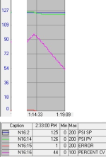
Look at this section of the last trend posted:
Untitled.png
In that trend, from 1:14:33 and 1:19:09, the [Percent CV] value dropped from 45%+ to 27% almost linearly over time, which means the PID and the PLC were sending a signal to the valve positioner to close the valve.

And over that same time span, from 1:14:33 and 1:19:09, the [PSI PV] dropped initially, then held steady at a value a PSI or so below the setpoint.

So the PID commanded that the valve be closed by over 18% to raise the measured pressure to setpoint by restricting the outflow of oil from the pressure vessel, while the pump moved oil into the pressure vessel at what we can assume is a near-constant rate.

This behavior persisted for over four and a half minutes i.e. two-hundred seventy seconds, which is nearly thirty times longer than it takes the valve to go from fully open to fully closed.

That's the background. There is no complicated math so I am going to assume you understand all of it; if not, just ask. So here comes the punchline:

That attempt by the PID to restrict the flow apparently failed to raise the pressure at all for the entire ; in fact the pressure dropped a bit while the valve signal was initially decreasing.

Can you suggest any reason why the vessel pressure did not increase between 1:14:33 and 1:19:09 while the PID was sending a signal to the valve positioner to close the valve in order to restrict the outflow, which should increase the pressure?
 
1. Yes, I've read all of it..

November 1st, 2022, 12:27 PM #46 drbitboy
“The valve is not opening (i.e. passing flow) until CV% is around 24…”

Almost 1 month ago. Due all this month drbitboy tries to convey this idea to you in detail and patiently.

OK. I’ll try.
Imagine that you are driving a car, but the steering wheel does not have a reliable connection with the front wheels (play in the steering). When you turn the steering wheel for example 10 degrees, the wheels can turn 5 or maybe 15 ... who knows. In this case, you will not be engaged in driving the car (fit into the turn), but will be struggling with play in the steering.

By the way, does the valve make extraneous sounds or shocks during operation?

3. The last two charts I posted used 500 msec as the update rate on the trend, .

I mean scaling not along the time axis, but along the VALUE axis. In your graph #85, the value of the process is "hidden in pixels" - I cannot determine the PV values accurately enough.
 
@MaxK and drbitboy. You are both pulling teeth and they won't come loose.
This is a problem that could probably be solved with a couple of short Skype or Zoom meetings. The OP doesn't seem to understand and certainly is not prepared to figure out an optimal solution.

I could have had this done in a few hours at most and this thread has been going on for a month. This thread has turned into yet another "Paula learning by doing thread".

This is what drbitboy referred to many threads back.
https://www.youtube.com/watch?v=Zu3MC4LJpu8&t=11s
One can model the valve with a little effort but lots of know how. You can then see what is necessary to compensate for the non-linear valve. The OPs valve just needs to operate from about 24% to 100% so this project is MUCH simpler in that the valve only needs to control around the edge of the spool or whatever is controlling flow.

I SMH
 
Look at this section of the last trend posted:In that trend, from 1:14:33 and 1:19:09, the [Percent CV] value dropped from 45%+ to 27% almost linearly over time, which means the PID and the PLC were sending a signal to the valve positioner to close the valve.

And over that same time span, from 1:14:33 and 1:19:09, the [PSI PV] dropped initially, then held steady at a value a PSI or so below the setpoint.

So the PID commanded that the valve be closed by over 18% to raise the measured pressure to setpoint by restricting the outflow of oil from the pressure vessel, while the pump moved oil into the pressure vessel at what we can assume is a near-constant rate.

This behavior persisted for over four and a half minutes i.e. two-hundred seventy seconds, which is nearly thirty times longer than it takes the valve to go from fully open to fully closed.

That's the background. There is no complicated math so I am going to assume you understand all of it; if not, just ask. So here comes the punchline:

That attempt by the PID to restrict the flow apparently failed to raise the pressure at all for the entire ; in fact the pressure dropped a bit while the valve signal was initially decreasing.

Can you suggest any reason why the vessel pressure did not increase between 1:14:33 and 1:19:09 while the PID was sending a signal to the valve positioner to close the valve in order to restrict the outflow, which should increase the pressure?

Yes, the approximate 10-13% backlash observed at the valve. The transducer changes signal to respond, but the valve does not change position, and indeed can fluctuate in it's position (even with a steady signal to the transducer) just due to the flow and pressure of the oil. New actuators with positioners are being ordered.
 
Hey, and less than a hundred posts to see the penny drop!

OT:

Though many may think it a waste of time, this could be seen as an interesting case of "the PLC cares not a whit ...," modified to be "the process cares not a whit ..."

The origin of this thread is that the model OP had for the process did not match the behavior they were seeing, and they suspected the PID was the issue. Not a bad suspicion on the face of it, because a mis-tuned PID can easily be the cause of process cycling. But within an hour of seeing the first trend, the first halting steps toward the answer (process dead band i.e. delayed valve opening) were taken, and the PID was seen to be performing exactly as designed and expected.

In other words, we built a model of the process based on what we knew about the process; as more data were provided, the model improved. Having a model of the process is critical. I have seen many on this forum, and my brother IRL, excel at it; I am not very good at it as can be seen by my many harebrained forays in this forum (to the amusement of @Peter N. and others, I am sure ;)). I hope I occasionally make up for that lack with persistence.

The final observation of physical backlash at the valve was an anti-climax because the process had already demonstrated same thirty posts earlier (also three weeks, but as OP mentioned early on, opportunities for testing would be many days apart, so those three weeks are not surprising).

Anyway, @Robb B, thanks for the feedback!
 
There are three things that really screw up pressure control. One is the dead band of the valve. It should be 0 for good pressure control but in this case the valve was only used to bleed off pressure. This allows the valve operate using only one edge of the spool. The second thing is hysteresis. If the spool doesn't respond to control changes within a percent, the pressure control will not be good. If Robb B means hysteresis is 13% then that is WAY TOO MUCH and you don't have a chance. The 3rd thing is not having spool feed back. If you don't know were the spool is you don't have a chance. Spool feed back is very important for hydraulic systems because the flow will cause Bernoulli effects that try to move the spool. The valve amplifier usually has a PI controller built in so that when the controller sends a 50% signal, the spool moves to the 50% position. This will mean you get 50% flow IF the valve is linear. If the valve is non-linear and there is a dead band then all bets are off. I have a pdf library of servo and servo quality proportional valves. One of the first thing I ask is what servo valve are you using?
This could have been solved long ago with the right equipment and knowledge.

Yes, right equipment and knowledge is great! Hopefully with everything I've learned here, the actuator being ordered is correct (0.1% hysteresis, with positioner and an analog output for external feedback), complete with new valve body.

Thanks again everyone for their help and information! I will try to remember to update this with a trend after the new valve is installed. (12 weeks away, minimum)
 
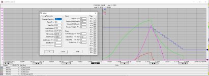
New Valve installed, first attempt at pressure cycle. Aborted the cycle (the dropping output/process value) due to a cylinder leak. There's still a lot of overshoot, but we are using the same values that were in the original valve.

Updated for entertainment!

Pressure cycle 2023 04 12 - P 1.5 I 0.5 D 0.0 - overshoot.jpg
 
New Valve installed, first attempt at pressure cycle.
There's still a lot of overshoot, but we are using the same values that were in the original valve.

I’m confused a little bit. CV reaches almost 70% and no visible process reaction…
Is the valve really working? Properly connected to the PLC? Is it possible to check the actual position of the valve?
 
I’m confused a little bit.
Me too
CV reaches almost 70% and no visible process reaction…
Yes, WTF?
Is the valve really working? Properly connected to the PLC? Is it possible to check the actual position of the valve?
A lot of valves that have on board electronics and a LVDT for spool posiiton feedback have a +/- 10 volt output that can be monitored.
A true servo valve would not have these problems.

@Robb B. What is the model of the new valve? Post a link to its documentation.
This could have done a long time ago with the right equipment.
 
Well it helps to have the air on when testing... Proper testing had great results. Will hopefully have a graph later today.

Peter, I will try to find a link to the valve/actuator assembly. I have charts from the build testing, would that be what you want? The new valve controller does have position feedback, which I have to wire into the plc still.

Valve: v8 th0200sxx9 https://a-tcontrols.com/Documents/314/VM.pdf
Actuator: Jamesbury QPX1C/MC https://www.valmet.com/flowcontrol/...bury-quadra-powr-x-series-pneumatic-actuator/
 
Last edited:
A ball valve will not be linear. The documentation shows that there is little if any flow when the valve has a small control signal.
I had to go back to the beginning to see what is being controlled. This should be easy. There are pressure regulating pneumatic valves that would make this easy. I think you are using the wrong equipment. The SLC5/05 should be doing the pressure PID, it should only be providing the pressure set point. The valve should regulate the pressure depending on the set point from the PLC.
Some of the pressure regulating valves can be very fast but a lot depends on the flow vs volume.
SMC and Enfield are two companies that make valves that should do what you want.
 
Last edited:
Peter, right now, the set point comes from the operators, via the HMI screen. The PLC uses this setpoint in the PID, and puts out the 4-20mA to the valve controller for open position (0-100%). There's only terminals for the analog signal in and signal out (position feedback).

In the attached picture, the operators wanted a slower pressure build so they can monitor tank levels, so I used a minimum 21% open.

Pressure cycle 2023 04 13 - P 5.0 I 0.5 D 0.0 CV Min 21.jpg
 

Similar Topics

Hello, I'm having a lot of trouble tuning a PID loop on a SLC 5/05. Can someone tell me if I'm doing something wrong? Please see attachment to...
Replies
8
Views
3,823
Hi, I have a system (see attached illustration) that is PID controlled. The pump is used for the injection of chemical from the tank to the...
Replies
5
Views
4,574
Hello, I am using a AB SLC5/05 PLC & using the PID insrtuction for a single loop control. I have assigned N10:0 as the control block starting...
Replies
4
Views
4,958
Hello, I am attempting to tune a PID loop on a process. The process involves a valve with electronic actuator that has quite a high deadband...
Replies
10
Views
2,159
so i have 4 25gpm wells feeding a 1000gal tank (T-1), with an additional 15gpm from a decant tank for 3hrs every 12hrs. P1 and P2 both controlled...
Replies
154
Views
35,868
Back
Top Bottom