You are not registered yet. Please click here to register!


plc storereviewsdownloads
This board is for PLC Related Q&A ONLY. Please DON'T use it for advertising, etc.
 
Try our online PLC Simulator- FREE.  Click here now to try it.

New Here? Please read this important info!!!


Go Back   PLCS.net - Interactive Q & A > PLCS.net - Interactive Q & A > LIVE PLC Questions And Answers

Reply
 
Thread Tools Display Modes
Old October 31st, 2022, 04:18 PM   #31
Robb B
Lifetime Supporting Member
Canada

Robb B is offline
 
Join Date: Feb 2011
Location: BC, Canuckistan
Posts: 290
Quote:
Originally Posted by drbitboy View Post
Whoa, thanks!

Is the stilling pipe used for a level measurement?
no, only for pressure, vacuum and level switches (ignored by operators )
Quote:
Is the stilling pipe slotted or perforated down its sides inside the treating vessel?
no, it is external to the vessel, and is plumbed in near the bottom on a fitting.

Quote:
Does the oil level reach the top of the treating vessel, or even go up into the extension of the stilling pipe above the vessel?
see above re: operators, but ideally, no oil should be present above the highest point of the vessel, ie: the ceiling.
  Reply With Quote
Old October 31st, 2022, 04:21 PM   #32
drbitboy
Lifetime Supporting Member
United States

drbitboy is offline
 
drbitboy's Avatar
 
Join Date: Dec 2019
Location: Rochester, NY
Posts: 6,414
What is the rate of pressure rise just before the control valve opens? e.g. how long does it take for the PV to increase the last 5 or 10psi before it reaches the setpoint?
__________________
_
Brian T. Carcich
i) Take care of the bits, and the bytes will take care of themselves.
ii) There is no software problem that cannot be solved with another layer of indirection.
iii) Measurement is hard.
iv) I solemnly swear that I am up to no good
v) I probably have the highest ratio of forum posts to actual applications in the field (∞).
vi) Hakuna matata.
  Reply With Quote
Old October 31st, 2022, 04:34 PM   #33
drbitboy
Lifetime Supporting Member
United States

drbitboy is offline
 
drbitboy's Avatar
 
Join Date: Dec 2019
Location: Rochester, NY
Posts: 6,414
Quote:
Originally Posted by Robb B View Post


[the stilling pipe] is external to the vessel, and is plumbed in near the bottom on a fitting.


Quote:
Originally Posted by drbitboy View Post
Does the oil level reach the top of the treating vessel, or even go up into the extension of the stilling pipe above the vessel?
see above re: operators, but ideally, no oil should be present above the highest point of the vessel, ie: the ceiling.

So is there air compressed into region at the top of the vessel, separate from the air at the top of the stilling pipe?

Because the treating vessel is initially full of air e.g. when the wood to be treated is placed inside, and then the vessel is somehow sealed before the process starts pumping oil into it? If yes, then once the oil level inside the vessel covers the stilling pipe fitting near the bottom, there are two separate air pockets, one in the vessel, one in the stilling pipe?
__________________
_
Brian T. Carcich
i) Take care of the bits, and the bytes will take care of themselves.
ii) There is no software problem that cannot be solved with another layer of indirection.
iii) Measurement is hard.
iv) I solemnly swear that I am up to no good
v) I probably have the highest ratio of forum posts to actual applications in the field (∞).
vi) Hakuna matata.
  Reply With Quote
Old October 31st, 2022, 04:43 PM   #34
Robb B
Lifetime Supporting Member
Canada

Robb B is offline
 
Join Date: Feb 2011
Location: BC, Canuckistan
Posts: 290
Quote:
Originally Posted by drbitboy View Post
So is there air compressed into region at the top of the vessel, separate from the air at the top of the stilling pipe?

Because the treating vessel is initially full of air e.g. when the wood to be treated is placed inside, and then the vessel is somehow sealed before the process starts pumping oil into it? If yes, then once the oil level inside the vessel covers the stilling pipe fitting near the bottom, there are two separate air pockets, one in the vessel, one in the stilling pipe?
That's very likely, as the vessels sit with a very slight (~1 degree) slope downhill to the drain, which is approximately the same place as the stilling pipe, 2/3 of the way down the vessel. If I had to guesstimate, I'd say there was about 6" of elevation difference over the 150 feet or whatever the vessel is long. There is a vent valve which opens while the vessel is filling or draining.

There is a level switch that is supposed to automatically shutoff the fill pump but I think they've been running it in manual for years now. I did test those switches last year and they worked fine.
  Reply With Quote
Old October 31st, 2022, 04:45 PM   #35
Robb B
Lifetime Supporting Member
Canada

Robb B is offline
 
Join Date: Feb 2011
Location: BC, Canuckistan
Posts: 290
Quote:
Originally Posted by drbitboy View Post
What is the rate of pressure rise just before the control valve opens? e.g. how long does it take for the PV to increase the last 5 or 10psi before it reaches the setpoint?
Hopefully I can catch a few pressure cycles over the next 24 hours, and we can estimate it from that. The general shape at 165 psi was a distinct S curve when pressure reached the setpoint, at 125 psi, it's much more vertical at the point that the pressure reaches the setpoint.
  Reply With Quote
Old October 31st, 2022, 05:34 PM   #36
drbitboy
Lifetime Supporting Member
United States

drbitboy is offline
 
drbitboy's Avatar
 
Join Date: Dec 2019
Location: Rochester, NY
Posts: 6,414
Quote:
Originally Posted by Robb B View Post
That's very likely, as the vessels sit with a very slight (~1 degree) slope downhill to the drain, which is approximately the same place as the stilling pipe, 2/3 of the way down the vessel. If I had to guesstimate, I'd say there was about 6" of elevation difference over the 150 feet or whatever the vessel is long. There is a vent valve which opens while the vessel is filling or draining.

WHUT?


how does the vessel pressurize if there is an open vent valve?


What is the diameter of the treating vessel?


What is the diameter and length of the stilling pipe?


- Dr Bitboy, DMD.
__________________
_
Brian T. Carcich
i) Take care of the bits, and the bytes will take care of themselves.
ii) There is no software problem that cannot be solved with another layer of indirection.
iii) Measurement is hard.
iv) I solemnly swear that I am up to no good
v) I probably have the highest ratio of forum posts to actual applications in the field (∞).
vi) Hakuna matata.

Last edited by drbitboy; October 31st, 2022 at 06:22 PM.
  Reply With Quote
Old October 31st, 2022, 05:56 PM   #37
drbitboy
Lifetime Supporting Member
United States

drbitboy is offline
 
drbitboy's Avatar
 
Join Date: Dec 2019
Location: Rochester, NY
Posts: 6,414
Quote:
Originally Posted by Robb B View Post
...The general shape at 165 psi was a distinct S curve when pressure reached the setpoint, at 125 psi, it's much more vertical at the point that the pressure reaches the setpoint.

That sounds like 165PSI is near the upper limit of head for the pump i.e. behind the knee of the curve with low flow and very large fractional change in flow for a small change in head, while 125PSI is past the knee where there is still a large flow.
__________________
_
Brian T. Carcich
i) Take care of the bits, and the bytes will take care of themselves.
ii) There is no software problem that cannot be solved with another layer of indirection.
iii) Measurement is hard.
iv) I solemnly swear that I am up to no good
v) I probably have the highest ratio of forum posts to actual applications in the field (∞).
vi) Hakuna matata.
  Reply With Quote
Old November 1st, 2022, 04:34 AM   #38
MaxK
Member
Czech_Republic

MaxK is offline
 
Join Date: Jul 2022
Location: FrozenHell
Posts: 120
Quote:
Originally Posted by Robb B View Post
The pressure applied is not constant, as it builds from 0 PSI to setpoint in a bit of an S curve.
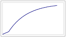
Is pressure curve looks this way: almost linear at the beginning then k(1-exp(-t/T))-shaped ?
Attached Images
File Type: png Pvess.png (1.7 KB, 47 views)
  Reply With Quote
Old November 1st, 2022, 08:50 AM   #39
jamesau
Lifetime Supporting Member
United States

jamesau is offline
 
Join Date: Mar 2004
Posts: 181
If 125psi is the new normal target operating point, consider a smaller impeller for the pump. If you expect multiple pressure operating targets, consider a vfd for the pump motor.
  Reply With Quote
Old November 1st, 2022, 10:24 AM   #40
Robb B
Lifetime Supporting Member
Canada

Robb B is offline
 
Join Date: Feb 2011
Location: BC, Canuckistan
Posts: 290
Quote:
Originally Posted by drbitboy View Post
WHUT?


how does the vessel pressurize if there is an open vent valve?


What is the diameter of the treating vessel?


What is the diameter and length of the stilling pipe?


- Dr Bitboy, DMD.
The vent valve closes while doing the pressure or vacuum cycles. It is only open while the vessel fills or empties. The diameter is approximately 8', length is approximately 180'. Stilling pipe is 3" diameter, runs about 15' from the vessel fitting to the pressure/vacuum sensors.
  Reply With Quote
Old November 1st, 2022, 10:29 AM   #41
Robb B
Lifetime Supporting Member
Canada

Robb B is offline
 
Join Date: Feb 2011
Location: BC, Canuckistan
Posts: 290
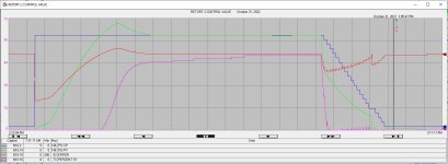
Here's a typical pressure cycle. The initial pressure is where we have issues, the end of the cycle is a stepped bleed-off of pressure, which is working fine. As the graph shows, there is no positive CV action until the setpoint is crossed, calculated error is ranged -200 to +200, I could re-do with greater ranges if it would help.
Attached Images
File Type: jpg Pressure cycle 2022 11 01.jpg (161.8 KB, 44 views)
  Reply With Quote
Old November 1st, 2022, 10:30 AM   #42
Robb B
Lifetime Supporting Member
Canada

Robb B is offline
 
Join Date: Feb 2011
Location: BC, Canuckistan
Posts: 290
Quote:
Originally Posted by jamesau View Post
If 125psi is the new normal target operating point, consider a smaller impeller for the pump. If you expect multiple pressure operating targets, consider a vfd for the pump motor.
The 125psi target might (will!) change in the future, I'd like to design the system to respond better to any future setpoints that might be implemented.
  Reply With Quote
Old November 1st, 2022, 10:44 AM   #43
Peter Nachtwey
Member
United States

Peter Nachtwey is offline
 
Peter Nachtwey's Avatar
 
Join Date: Apr 2002
Location: The land of the woke and the home of the broke
Posts: 8,153
Quote:
Originally Posted by drbitboy View Post
A 40HP constant-speed pump (re-read the OP) for a PILOT valve? Really?
my first assumptions where wrong. It was hard to visualize the system after just the first post. The differential equation that I posted before doesn't apply. After seeing the diagram it is clear that the P*V=n*R*T is the way to go The air in the treatment vessel is more like an accumulator in hydraulics.
Anyway the pressure doesn't change linearly with level and if the pump is a centrifugal pump, the pump flow will vary with pressure. At the new lower pressure the pump flow will increase which will increase the pressure faster but this may be offset by the increased air volume will tend to reduce the rate of change in the pressure.

It should be possible to get reasonable control with just a P gain. There will be an offset but then an integrator can fix that.
I don't see why the system is so difficult to control.
Any this thread has exceeded the 20 questions limit.

weird system.
__________________
"Living is easy with eyes closed, misunderstanding all you see...." Strawberry Fields Forever, John Lennon
  Reply With Quote
Old November 1st, 2022, 10:48 AM   #44
drbitboy
Lifetime Supporting Member
United States

drbitboy is offline
 
drbitboy's Avatar
 
Join Date: Dec 2019
Location: Rochester, NY
Posts: 6,414
Quote:
Originally Posted by Robb B View Post
[Vessel] diameter is approximately 8', length is approximately 180'. Stilling pipe is 3" diameter, runs about 15' from the vessel fitting to the pressure/vacuum sensors.
The bulk modulus of the air in the stilling pipe may contribute, but it is likely less important than bulk modulus of the oil, I would guess the relative oil:air contribution to the pressure vs. volume behavior is somewhere between 2:1 AND 20:1, unless the oil is hydraulic oil, in which case it may be 1:1.
__________________
_
Brian T. Carcich
i) Take care of the bits, and the bytes will take care of themselves.
ii) There is no software problem that cannot be solved with another layer of indirection.
iii) Measurement is hard.
iv) I solemnly swear that I am up to no good
v) I probably have the highest ratio of forum posts to actual applications in the field (∞).
vi) Hakuna matata.
  Reply With Quote
Old November 1st, 2022, 10:57 AM   #45
drbitboy
Lifetime Supporting Member
United States

drbitboy is offline
 
drbitboy's Avatar
 
Join Date: Dec 2019
Location: Rochester, NY
Posts: 6,414
Quote:
Originally Posted by Peter Nachtwey View Post
my first assumptions [were] wrong.
Join the club; we're having jackets made up.

Quote:
Originally Posted by Peter Nachtwey View Post
It should be possible to get reasonable control with just a P gain. There will be an offset but then an integrator can fix that.
I don't see why the system is so difficult to control.
Any[way] this thread has exceeded the 20 questions limit.

weird system.
^this

Yeah, I suggested stiff P-only control over two dozen posts ago (#18).
Quote:
Originally Posted by Peter Nachtwey View Post
After seeing the diagram it is clear that the P*V=n*R*T is the way to go The air in the treatment vessel is more like an accumulator in hydraulics.
I thought so too for some time, but consider that the vessel is vented until it is full of oil, and look at the final liquid:gas volume ratio: 106-107; PV = nRT is out the window.

This is more like a hydraulic system, perhaps with some undissolved air, so it's solidly in @Peter Nachtwey's wheelhouse.
__________________
_
Brian T. Carcich
i) Take care of the bits, and the bytes will take care of themselves.
ii) There is no software problem that cannot be solved with another layer of indirection.
iii) Measurement is hard.
iv) I solemnly swear that I am up to no good
v) I probably have the highest ratio of forum posts to actual applications in the field (∞).
vi) Hakuna matata.

Last edited by drbitboy; November 1st, 2022 at 11:28 AM.
  Reply With Quote
Reply
Jump to Live PLC Question and Answer Forum


Currently Active Users Viewing This Thread: 1 (0 members and 1 guests)
 
Thread Tools
Display Modes

Posting Rules
You may not post new threads
You may not post replies
You may not post attachments
You may not edit your posts

BB code is On
Smilies are On
[IMG] code is On
HTML code is Off

Forum Jump

Similar Topics
Thread Thread Starter Forum Replies Last Post
PID Position to Velocity Equation Tuning Parameter Conversion JLand LIVE PLC Questions And Answers 7 January 18th, 2022 05:15 PM
SLC 5/05 Communication Problem with Serial Port.. pranav.mistry003 LIVE PLC Questions And Answers 2 August 23rd, 2012 03:41 PM
Reading L32E with SLC 5/05 24fretslater LIVE PLC Questions And Answers 7 February 23rd, 2012 11:26 AM
Control Slc 5/04 PID The Plc Kid LIVE PLC Questions And Answers 1 August 6th, 2009 03:41 PM
SLC 5/05 PID Time Mode Question Dwarfer1 LIVE PLC Questions And Answers 7 December 15th, 2004 04:52 AM


All times are GMT -4. The time now is 11:54 PM.


.