Array Data Being Overwritten

Astleas

Member
Join Date
Jun 2022
Location
USA
Posts
11
Hi all,

I've got a PLC program that's supposed to read the data of the individual ports on a Stratix switch (for example, the MAC address) through CIP messaging and then store this data in an array of UDTs that represent the switch port. The structure of the program is as follows:

0) There are two controller tags: Port_Index and Last_Port_Index that represent the index of the port that is currently being read and the index of the port that was last read, respectively. These start at 1 and 0, respectively.

1) There is a rung with a label called Port_Message_Trigger. It checks to see if Port_Index is not equal to Last_Port_Index. If this evaluates to true, the rest of the rung will copy Port_Index into the Instance parameter of the MSG instructions, which pull the data from the port and push it into a UDT called Temp_Port.

2) The next rung checks to see if Port_Index is equal to Last_Port_Index. If this evaluates to true, Port_Index is incremented by 1, or if it is already at the maximum (26, representing the 26 ports on the switch), it is reset to 1. Then a jump instruction is called to go back to the rung labeled Port_Message_Trigger.

3) The next rung checks if the MSG instructions have completed and, if so, copies the data from Temp_Port into the array of UDTs at the index specified by Port_Index.

4) The next rung moves the value of Port_Index into Last_Port_Index.

5) The routine is executed again from the beginning.

The idea behind this program is that the Class and Attribute are identical for a specific parameter for any given port on the switch. The only thing that changes is the Instance number, which ranges from 1 to 26 according to the EDS. So the program will start at Instance 1, read the data, copy it into the UDT array at that index, update to show that Instance 1 has already been read, and then move on to the next Instance until it has read all 26 ports.

What I find happening, however, is that the indices in my array are being overwritten by data that matches to other ports. For example, the MAC address of Port 1 is XX-XX-XX-XX-XX-41. Port 2 is XX-XX-XX-XX-XX-42, and so on. After the program runs, what should happen is that index 1 of my array gets the MAC address ending with 41, index 2 gets 42, etc. What is actually happening is that every index is getting MAC 41, and then every index is getting MAC 42, and so on.

The copy instruction I have explicitly copies the values in Temp_Port into PortUDTArray[Port_Index], and to my understanding, Temp_Port should only ever be storing the data from the MSG instruction with the Instance at whatever Port_Index is during the current scan cycle. So I'm struggling to figure out why my data is constantly being overwritten.

What exactly am I missing here?
 
Can you post an image of the code for clarity?

EDIT: I am curious to see if for some reason Port_Index is getting cycled from 1-26 every scan for some reason. Perhaps a ONS somewhere could solve this problem.
 
Last edited:
Sure thing. I've attached pictures Rung 1 through Rung 4. They're in that order in the routine. The picture of rung 1 doesn't show all the message instructions; each subsequent message is set to trigger only when the previous is done or throws an error. The final one is VLANs_Assigned_MSG, which I'm using in Rung 3 as a proxy for "all messages complete," at which point the copy instruction should execute. It's currently a CPS instruction, but I've tried a COP as well, to the same effect.

Rung 1.PNG Rung 2.PNG Rung 3.PNG Rung 4.PNG
 
You're using COP or unneeded CPS with length 1. That 1 length is for the destination element. Try MOV.
 
You're using COP or unneeded CPS with length 1. That 1 length is for the destination element. Try MOV.

Thanks for the feedback, 5618. I don't think MOV instructions work for UDTs. At any rate, I just attempted it and the program wouldn't compile, giving an error for that rung.
 
Ah, yes, my bad. Too early in the day. Do you have a Rockwell developed AOI to use as reference to see how what you're doing is done there?

Edit: you might need to make sure the MSG.DN bit is true before copying the data, indexing, and looping to the JMP LBL.

Another edit: as I wake up, it looks like you're looping through the full array during one MSG. In the AOI, a local step cycles through messages. There is usually a substep that is set when the MSG is triggered, then when that substep is true and MSG is DN, copy the data, clear the substep, then move on to the next local step. I recommend dropping the JMP and creating steps to sequence messages and data copies.
 
Last edited:
I was wondering that as well, is there enough time for the .DN bit to be set? What if you latch a bit when the message is triggered and then unlatch it when the CPS is executed? Also, make sure that Port_Index isn't moved into Last_Port_Index until the message has been completed.
 
Thanks for the feedback, everyone.

MikeyN:

I created a "Message_Complete" bit to be latched in when the last message, VLANs_Assigned, is done and to be unlatched after the copy instruction. Then I added an XIC for this bit to the rungs that execute the copy instruction and increment the index, but this has the same effect as the original program.

widelto:

Sorry for the confusion; VLANs_Assigned_MSG is part of Rung 1 but not included in the screenshot because that rung has too many MSG instructions to fit in a single picture (and still be readable). That message is done when the chain of messages starting with MAC_Address_MSG finishes, all on Rung 1.

5618:

Could you explain a little more about this substep idea? I'm not entirely sure I follow. I was under the impression that what I have in Rung 1 should only ever execute once in a single scan, when the index of the current port and last port are not equal. The two values become equal in Rung 4, so once it gets back to Rung 1, that rung shouldn't be executed. Then Rung 2 will execute to increment the current port index, then jump back to Rung 1 to execute the messages for the current index. Am I wrong in this assessment?
 
Based on the description, you are using RA supplied Stratix AOI.
If yes, then do you have more than one instance of AOI?
Again, if you do, then check the destination tag of each message of each AOI. If you used Copy/Paste instead of recommended Import, then Message Destination tag is most likely was not replaced and this causes data overlap.

Better to put your code here.

And if you are not using Rockwell AOI, then you should :)


Thanks for the feedback, Contr_Conn,

No, I'm not using the Rockwell AOIs for this. My specifications for this task were to pull every piece of data from the switch that was available through explicit CIP messaging, many of which were not accounted for by Rockwell's pre-built instructions. To this end, I've written my own logic, the idea behind it being to essentially loop through every Class/Instance/Attribute combination in the EDS file that is directly addressable by the network.
 
I recommend you at least check out the Stratix AOIs if you haven't. They're designed to be used with a Stratix faceplate on a PanelView, but I only use that on one system. I can see good reasons to roll your own if you only need part of what the AOIs do. My experience is mainly with an older version with 5700 and a separate one from the same era for 2500. A newer version has the HMI data as internal tags, not accessible in the PLC without extra steps.

The substep in the AOI is basically a MSG in progress bit. At the beginning of a localStep, MSG parameters are set to the next thing in sequence, MSG is triggered and substep is set.That keeps the MSG parameters from uselessly updating again and anything else undesired on that branch next scan. When MSG.DN and that bit are on, process the returned data, increment to the next step and unlatch the bit. Look at the AOI.

Edit: you posted while I was composing. Interesting and fun. Please report back some interesting findings.
 
Last edited:
@Astleas: step back a bit.
Axiom 1: I can say with 100% confidence that, unless there is something broken in that unit, the PLC is doing exactly what you told (programmed) it to do.
Assume for the moment I am not some wiseguy bozo on the Internet (not usually a good assumption, especially about me, but humor me for a second), let Axiom 1 sink in for a minute, and think about what the implications are.

Specifically, since I am also fairly certain that, when you were writing that code, you had a model in your head about what actions the PLC would be doing, and when it would do them, as it executes that code, one implication of that [Axiom 1] is that you have a faulty model about how a PLC executes instructions. Once you fix that model, the problem, as well as a likely path to a solution, will become clear.

TL;DR

The structure of the program is as follows:

0) ...
1) ...
2) ...
3) ...
4) ...
5) The routine is executed again from the beginning.

@Astleas: what is your level of PLC programming knowledge and experience?

I ask because the code in the images posted suggests a common, but fundamental, misunderstanding of the PLC scan cycle.

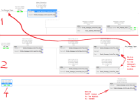
Let's look at the rungs 1, 2 and 4 (see image below), and how, and more interestingly when, they modify the values of index and last_index..

  • On Rung 1,
    • Case 1.NEQ: if index and last_index are not equal, then the MSG is triggered.
    • Case 1.EQU: If index and last_index are equal, then the MSG is not triggered
  • On Rung 2,
    • Case 2.EQU: if index and last_index are equal, then index is incremented, with wraparound from 25 to 1
      • AND control is transfered back to Rung 1 via the JMP, where Case 1.NEQ is followed,
        • because the incrementing of index on this Rung 2, when index and last_index were equal, means that index and last_index,are no longer equal.
    • Case 2.NEQ: if index and last_index are unequal, then nothing is done
    • In either case, on exiting this Rung 2, index and last_index will never be equal, whether we went back to Rung 1 and then dropped though Rung 2 the second time, or not
  • On Rung 4,
    • last_index is set equal to index
    • So on the next scan ("5) The routine is executed again from the beginning." - Astleas), we start with index equal to last_index.
What exactly am I missing here?


After the first pass, when index is 1 and last_index is 0, every pass through this routine starts with index equal to last_index. So Rung 1 will do nothing at the very start, but then Rung 2 will make them unequal and JMP back to Rung 1 for a second attempt, which *will* do something, and finally Rung 4 will make them equal again just before the next pass when we start again with Rung 1.

Also note that index will increment on every scan, as will last_index because of Rung 4. This will happen several hundred or maybe one-thousand times per second. A single execution of the MSG command, which will start with the first rising edge of its input rung, is asynchronous with the scan cycle, and will likely take several scans, maybe as many as 26, to complete. While that MSG instruction is waiting to complete, Rung 3 (not shown here) is merrily copying Temp_Port to whatever element of the [Newell_Switches] array the [index] is telling it to write to, and since we already established that [index] is incrementing though one new value of the range 1 to 25 (never 26, btw ;)) on each scan, every element of the [Newell_Switches] array ends up with the same values i.e. whatever is in Temp_Port until overwritten by the next MSG completion.

The scan cycle executes the rungs top to bottom, in order, and left to right and top to bottom on each rung. and then repeats that execution order again from the top, ad infinitum. So this program would execute exactly the same if you put current Rung 4 above Rung 1.


Now, maybe I have this wrong, and this is a routine that is called (JSRed?) on some trigger. But based on what you wrote, and the symptoms we are seeing, maybe I am not the bozo (this time, anyway).
Rungs.png
 
Last edited:
Additional comment:

  • in ladder logic, the scan cycle ensures that every rung is executed at least 10 times per second*.
  • That being the case, a JMP backwards to an earlier rung is almost never required**, because it is usually good enough that the earlier rungs will be executed on the next scan.
    • An alternative to the backwards JMP in this case would be to swap Rungs 1 and 2, i.e. execute current Rung 2 before current Rung 1: functionally this would execute essentially the same; the only difference being that the MSG would see its rising edge on the first (and only) time it the scan cycle executes its rung.
  • So why you used that backwards JMP will be the key to identifying, and correcting, the faulty model of how PLCs run a scan cycle that is in your head (and again, I could be completely wrong).

* typical maximum scan times are 100ms
** or only required in special situations i.e. a loop.
 

Similar Topics

Hello, I have an int variable that updates the value every second. I want to store the 100 values in an array. Array should keep storing the...
Replies
7
Views
999
Hello, I'm digging all over the internet to find a solution for this but haven't come up with anything yet. We have 3 nearly identical machines...
Replies
2
Views
958
Hello! I am completely new to PLCs, so I apologize in advance if this is a dumb question. I have a device that sends out its data as a number of...
Replies
5
Views
2,130
hi i have a baumer vision unit picking up a QR code this is connected to a siemens 1200 plc. i have a IB18 In the device that is the start of...
Replies
16
Views
9,315
I'm using the latest Rockwell CCW to program a Micro 850 and Panelview PV800 - 2711R HMI. I'm having difficulties getting the Panelview HMI tags...
Replies
1
Views
1,817
Back
Top Bottom