HMISCU8B5 4-20ma wiring question.

Boyler3

Member
Join Date
Dec 2021
Location
Pittsburgh
Posts
19
Hi All,


I have a question about the input wiring on a HMISCU8B5. I am so close to having what I am after yet it seems so far away. I have attached a picture of what I am doing and it works fine as long as I hook only one of the 4-20ma inputs at a time. I want the HMISCU8B5 to take the place of the Kele LPI-1C's. I have to be missing something on the attached wiring diagram. How can terminal (D12) C2 be the same for both 4-20ma feedbacks? Like I said either or works fine by itself, meaning my JCI controller sees the same thing the HMI sees when either input is hooked up by itself. I just don't understand how this wiring schematic could work for two different 4-20ma signals. If anyone has any information or suggestions please let me know. Thanks.
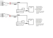
HMISCU8B5 wiring.jpg
 

Attachments

  • Kele LPI-1C typical panel mount.pdf
    155.9 KB · Views: 16
I'm guessing that (C14) AIC1 or D13 AIC0 is the Analog input's (+) positive terminal.

I'm not sure why (C12) AIV1 or C13 A1V1, probably a voltage input, is jumpered to AIC0/AIC1.

(D12) C2 appears to be the Analog input's (-) negative input.

Your field transmitter conductor labeled #2 is the positive signal conductor, even though it comes off the (-) transmitter terminal, it is the most positive connection (more positive than the power supply (-) terminal)

Your field transmitter conductor labeled #1 is the negative signal conductor.

Make sure signal (+) goes to AI (+), and that signal (-) goes to AI (-)

Current inputs need a resistor at the input to convert the current to voltage.

Sometimes that resistor is built into the analog input. Sometimes it needs to added externally across the AI (+) and (-). Does the documentation mention external droppoing or shunt resistors?
 
Here is the link to the documentation on this HMI https://www.electrocentr.com.ua/files/documentation/SE/hmi/guide/HMI_SCU_Hardware_Guide_2016.pdf

I do not see anything about shunts. I just do not get why it shows C2 being used twice as what seems to me to be the feedback. Not sure about the whole jumper thing but it does work for either of the 4-20ma inputs. It just don't / can't work for both. It seems like there should be another terminal besides C2 to send a 2nd signal back.
 
Draw your circuit with one Power Supply, 2 transmetteurs 2 wires, 2 inputs and one comm. Your understand, i am sure! the currant read is the current in the terminal Ai+.
 
Sorry Pasbra. Not sure exactly what you mean. I am by no means an electrician, just a building automation person that is used to seeing a typical 4-20ma setup.
 
D12/C2 connects to #1 and #3


D13/AIC0 connects to #2


C14/AIC1 connects to #4


Page 133 says you have to configure that type of input.
 
Thanks danw. I will give it a shot. I know that my configuration of the inputs are correct because I could get each of them to work one at a time. My HMI display was reading real close to what my JCI controller was reading. I just hope that this does not somehow skew my readings at either side. I have been scratching my head for weeks now trying to figure out how this can work. The tech support has been having me go in circles. I figured I would reach out to others and just happened to find this forum. I will sketch out the designations that you are saying and give it a shot tomorrow when I get back on site. Thanks a million for your help and I will let you guys know how it goes.
 
One last thing danw. Do I leave C12 and C13 out of the picture or do I jumper them to D13 and C14 respectively, like they show in the wiring diagram?
 
For current signals, jumper the 'V' terminals to the 'C' terminals as shown in the wiring diagram.


And do not jumper C14 to D13, but that's not shown on the wiring diagram.
 
No. I meant jumper D13 to C12 and then jumper C13 to C14. I think we are on the same page. Thanks again. I will let you know how it goes.
 

Similar Topics

Hi all, I'm connecting several 4-20mA sensors together in parallel (only one shown below) The enclosure is ABS plastic with metal backplate DAQ...
Replies
5
Views
273
Problem: Our PLC can only output 4-20mA, but the actuators it needs to control, modulate based on a 0-135Ohm signal. Buying 4 or 8 individual...
Replies
7
Views
275
What's your go to 4-20ma isolator. I've got some 4 wire 4-20ma from several flow meters and scales that I would like to isolate before it gets to...
Replies
10
Views
1,688
Hi, I need to read three 4-20mA signals from a DCS(ABB) in a remote 6 channel analog input module with RS485 modbus port. When I connected...
Replies
2
Views
486
Hello this is my first post. Looking forward to being more involved in this community to learn and hopefully help others. Any help or guidance...
Replies
7
Views
790
Back
Top Bottom