M221 -> NB omron HMI comms

CMDRZOD

Member
Join Date
Feb 2022
Location
Alberta
Posts
9
Hi. First post here. Hoping to get some help with a m221 im using with machine expert basic to communicate with an omron HMI.

Im using Ioscanner with a TCP gateway to communicate to the HMI via Modbus TCP. I'm able to write values to the HMI without issue. The problem is that I encounter "thrashing" where my inputs are opening and closing like mad.

I was tinkering with poll rates in the channel settings in machine expert and am able to eliminate the thrashing by having read at say 250ms while write channel updates every 800ms.

I find this is not an ideal solution. The PLC will sometimes miss the input to true when write channel updates are scheduled over 500ms. I'm looking for a way to reliably write and read my digital variables to the HMI and back. Screen shots attached.

With the logic pictured, the button status will cycle between true and false indefinitely forever when I trigger the input true on the HMI. I am using a button on the HMI that will alternate states for the single button logic.

The dual button logic uses one button on and another button to turn off. It seems to be more reliable but still misses input sometimes and will not trigger the bit occasionally.

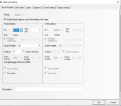
m221buttonlogic.png omronbuttonlogic.png omrondualbuttonlogic.png
 
Disclaimer: I dont know Omron

I'm looking for a way to reliably write and read my digital variables to the HMI and back.
What is it that you really need to achieve ?
That you cannot catch every blip of the inputs when you read is 500 ms should be obvious.
And you definitely do not write PLC inputs should be obvious to you.

Without knowing what you are trying to achieve, maybe you should let the PLC inputs update some counters, and your HMI then read the count values instead of the raw input states.
 
Hmm, hang on. You're using the M221 I/O scanner to read / write to the HMI?

Normally, I'd expect the PLC to be the Modbus TCP server, and the HMI reads / writes from the PLC
 
Agree with Saffa
I wouldnt use IO scanner for this purpose at all.
Discalimer: I havent use a tm221 with an Omron HMI before
Having said that the Omron HMI should have a modbus tcp/ip driver which will be fine to use without setting anything up in the plc.
 
Jesper is on the right track. The OP is trying to do something funky that has nothing to do with polling time and likely has to do with misunderstanding of what an HMI does. The button on an HMI do not behave as physical inputs.

If he explains what he want to do that would be best; and the rung in his first image looks funky.
 
I figured it out in my sleep. His description is that of toggle circuit and the rung looks like an attempt at a latching circuit.
 
Thats right.

It's my attempt at a holding circuit. When I press the button on the HMI I'm trying to hold the input true. Im using an alternate button on the HMI to turn the input to false on the second press.

The input only triggers true momentarily from the HMI. I want to hold it true until the next button press, which will trigger false.

The issue I''m having is missing the button press on the PLC and the output never becomes true even through the button was triggered. I am encountering the same on the second press. I get about 75% of presses registered at the PLC, but am looking for a better button input method.

My current modbus scan time is 50ms to try to pickup the input as reliably as possible.

Yes Im a noob at automation. I'm used to working on programs, not so good at writing my own.

I also tried a counter method, but with limited success. Any suggestions are welcome.
 
... the rung in his first image looks funky.

I figured it out in my sleep. His description is that of toggle circuit and the rung looks like an attempt at a latching circuit.


Brilliant; there seem to be two stages - detective stories - to most threads: (1) Figure out what the OP's problem is, from sketchy data; (2) solve OP's problem.

(then there is the third middle stage (1.5), where we gently and humorously berate OP for not providing enough information ;)).

Anyway, I think OP should be aware that this rung, which they provided:
m221buttonlogic.png
Is equivalent to this rung:
m221buttonlogic_equivalent.png
And they should look at this link, along with this and this as well.

However, assuming @kalabdel is correct, and OP wants %QN100.1.2 to change (invert; toggle; 0=>1 or 1=>0) state every time %IN100.0.2 has a rising edge (transitions from 0 to 1), then the following circuit may suffice. N.B. the first rung could be replaced by a one-shot (pulse? rising edge?) instruction.

m221buttonlogic_toggle.png
 
Thank you Drbitboy I will try this out. I am aware those rungs are the same. I added the other contacts to help reliably hold the bit true when triggered on the HMI.
 
It's my attempt at a holding circuit. When I press the button on the HMI I'm trying to hold the input true. Im using an alternate button on the HMI to turn the input to false on the second press.

The input only triggers true momentarily from the HMI. I want to hold it true until the next button press, which will trigger false.
And what has this to do with the original problem of sensing the inputs when they are "opening and closing like mad" ?
Anyway, I think what you are after is a "flip/flop". Search the forum for flip/flop and you should get several good hits.

In addition to the flip/flop functionality, also consider this:

1st, if the PLC address that is assigned to the button is really a PLC input, then you cannot do that at all. Assign an internal PLC memory address to the button.

2nd, having hold and release buttons on an HMI is not recommended. Any HMI or comms problem, and you may have a bit that wont turn off.
It is much more reliable and robust to
a, set the bit by the HMI upon the event that the button is pressed.
b, the PLC reads the status of the bit, performs the desired action if the bit is true, and resets the bit unconditionally.
 
Thats right.

It's my attempt at a holding circuit. When I press the button on the HMI I'm trying to hold the input true. Im using an alternate button on the HMI to turn the input to false on the second press.

The input only triggers true momentarily from the HMI. I want to hold it true until the next button press, which will trigger false.

The issue I''m having is missing the button press on the PLC and the output never becomes true even through the button was triggered. I am encountering the same on the second press. I get about 75% of presses registered at the PLC, but am looking for a better button input method.

My current modbus scan time is 50ms to try to pickup the input as reliably as possible.

Yes Im a noob at automation. I'm used to working on programs, not so good at writing my own.

I also tried a counter method, but with limited success. Any suggestions are welcome.


Okay, we are getting close, but I don't think we have all of the pieces of the puzzle yet. So here are some queries about this process. Maybe OP feels they answered them already and either I mis-read what they wrote, for which I apologize, or what they wrote I don't understand (e.g. what is an "alternate button?).

  • OP: please list the specific actions and specific responses OP wants to see, e.g.
    • When operator presses button X on HMI
      • Then output %QN100.1.2 should change (invert state) i.e.
        • either if %QN100.1.2 a 1, it should become 0,
        • or if %QN100.1.2 is a 0, it should become a 1
    • When operator releases button X on HMI
      • Nothing more should happen
  • How many buttons are there? I would assume from its name that %IN100.0.2 is a physical discrete input to the PLC, and not the bit read from the HMI, so the PLC may be re-writing that bit during the I/O portion of every scan (assuming PLC scans are synchronous with PLC I/O).
  • How do any HMI bits change when any HMI button of interested is maniuplated?
    • What happens when the HMI bit is 1 and the button is pressed, or can that even happen?
    • What happens when the HMI bit is 1 and the button is released, or can that even happen?
    • What happens when the HMI bit is 0 and the button is pressed, or can that even happen?
    • What happens when the HMI bit is 0 and the buttone is released, or can that even happen?
  • OP mentions Modbus.
    • What is being communicated via Modbus?
    • Which way is the communication going? Is the PLC the Modbus client making a read request, and getting are response from the HMI as the Modbus Server, or is something else happening?
    • What bit(s) is(are) is being read, if any?
    • What bit(s) is(are) being written, if any?
    • What bits are changing on the PLC as a result of the Modbus communication?
    • What triggers an individual Modbus request?
 
Thank you Drbitboy I will try this out. I am aware those rungs are the same. I added the other contacts to help reliably hold the bit true when triggered on the HMI.


But if you look at it closely and think like a PLC, you will see that those extra instructions (OR of NO100.0.2 %IN with NO %QN101.1.2) do not help at all, i.e. they cannot "reliably" hold the bitt, and in fact those extra branches do absolutely nothing at all.


"Holding the bit" is done with what is called a "seal-in," and the rung you showed is not a proper seal-in. Please refer to the links I sent: they illustrate best practice, and are used in some form again and again in ladder logic programming.
 
OP: please list the specific actions and specific responses OP wants to see, e.g.
When operator presses button X on HMI
Then output %QN100.1.2 should change (invert state) i.e.
either if %QN100.1.2 a 1, it should become 0,
or if %QN100.1.2 is a 0, it should become a 1

- Yes i want first press to trigger true and hold. Second press trigger false and hold.
When operator releases button X on HMI
Nothing more should happen <- correct. Release should not affect input
How many buttons are there? (1 button for testing) I would assume from its name that %IN100.0.2 is a physical discrete input to the PLC, (%IN100.0.x are input from HMI, QN are output to hmi) and not the bit read from the HMI, so the PLC may be re-writing that bit during the I/O portion of every scan (assuming PLC scans are synchronous with PLC I/O). <- Good point this is likely the case
How do any HMI bits change when any HMI button of interested is maniuplated?
What happens when the HMI bit is 1 and the button is pressed, or can that even happen? <- when button 1, next button press on same button triggers 0
What happens when the HMI bit is 1 and the button is released, or can that even happen? <- hoping for release of button to have no effect
What happens when the HMI bit is 0 and the button is pressed, or can that even happen? <- input to HMI should trigger true in this case
What happens when the HMI bit is 0 and the buttone is released, or can that even happen?
OP mentions Modbus.
What is being communicated via Modbus?<- HMI values being read and written from HMI, can read floats and ints but having issue with digital IO
Which way is the communication going? Is the PLC the Modbus client making a read request, and getting are response from the HMI as the Modbus Server, or is something else happening? <- Using IOSCANNER it polls inputs and output on modbus every 50ms
What bit(s) is(are) is being read, if any? Digital and words from PLC to HMI
What bit(s) is(are) being written, if any? HMI output (digital) to PLC
What bits are changing on the PLC as a result of the Modbus communication?
What triggers an individual Modbus request? <- IOScanner is set to 50ms updates.

Hope this clarifies a bit for everyone.
 
But if you look at it closely and think like a PLC, you will see that those extra instructions (OR of NO100.0.2 %IN with NO %QN101.1.2) do not help at all, i.e. they cannot "reliably" hold the bitt, and in fact those extra branches do absolutely nothing at all.


"Holding the bit" is done with what is called a "seal-in," and the rung you showed is not a proper seal-in. Please refer to the links I sent: they illustrate best practice, and are used in some form again and again in ladder logic programming.

Thank you am taking a look at those links now
 

Similar Topics

Hello, I need to access the bits from the fire system control panel through RS-485. So, I used Read Var block to read from the panel...
Replies
0
Views
187
Hi, I am using M221 reading from 3 different sensors (modbus rs485) sharing same bus (daisy chain). I am currently using READ_VAR (in total...
Replies
0
Views
84
Hi, I am stuck with these SE cartridges, I am trying to add a second serial port rs485 to a M221 PLC. What is the difference between TMC2CONV01...
Replies
1
Views
116
I am having trouble running the application throught my PLC, tm221me32tk with magelis HMIGTO6310 I have prepared the plc programme, also created...
Replies
0
Views
109
Hello all, I need to build a system that will operate various AC contactors and 'lock' them out for a predertimed time when a set current value...
Replies
6
Views
323
Back
Top Bottom