Unwinder

Isn't the normal thing to have one VFD/motor set the speed, and run the other VFD/motor at some fraction above or below that by some percentage but torque limited, so the torque limit will always be active and set the tension?

E.g. run the unwind VFD on speed control at speed SUW = linespeed/(UnwindDiameter*PI) RPM, and run the wind at speed SW = linespeed*105%/(WindDiameter*PI) with a torque limit of (TargetTension*WindDiameter/2), so the wind roll will always be applying a linear tension of TargetTension. It would be preferable to measure UnwindDiameter and WindDiameter, but modelling them would be another option.

Knowns

  • Ldot, m/minute, target line speed
  • De, m, unwind diameter when empty
  • Df, m, unwind diameter when full
  • Lf, m, linear length of material from full (Df) to empty (De)
Calculated and/or Modeled

  • RPM, revolution/minute, unwind rotation rate
  • θ, m, thickness of one layer on unwind
  • π, 3.14159...m/m, ratio of circumference of roll to its diameter
  • t, minutes, time of unwind
    • t = 0 at beginning, when unwind diameter is Df
    • t = Lf/Ldot at end, when unwind diamter is De
  • D, m, instantaneous diameter of unwind roll
  • L, m, instaneous linear length of material
    • L = Lf, at time t=0, when unwind diameter is Df
    • L = 0, at time t=Lf/Ldot, when unwind diameter is De
Models

  1. RPM = Ldot/D, revolutions/minute - calculate instantaneous RPM as a function of D, i.e. to yield linear speed of Ldot when unwind diameter is D
  2. D = SQRT(De**2 + (4 θ L / π)), m - calculate diameter of roll as a function of L i.e. of length of material left on roll
  3. L = Lf - Ldot t, m - calculate length of material remaining to unwind, as a function of time t
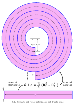
  4. θ = π (Df**2 - De**2) / (4 Lf), m - calculate average thickness of one layer, from known initial parameters
Calculate θ once from Model 4 at start of unwind process.

For any time t at and after that:

  • calculate L from t in Model 3,
  • calculate D from L and θ in Model 2,
  • calculate RPM from Model 1.
The unwind RPM will need to be converted (scaled) to a VFD/Motor speed motion command, modeling whatever gearbox or other physical drive is present.

The θ and D calculations, in Models 4 and 2 above, are based on the geometric area model in the first image below.

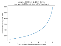
A sample plot of unwind RPM vs. t is in the second image below.

Caveats

  • I am not saying this model will work; this is just a model with the parameters the OP said they already have, plus an assumed known value for Lf.
    • Even the small [one part in 1e7] roundoff errors inherent in 32-bit floating point values from the calculation of θ could accumulate significant errors in D near the end of the unwind process
  • Assumes mean per-layer thickness, θ, is constant, and any variation averages out
  • Assumes total length to be unwound between Df and De is known, i.e. Lf
  • Assumes unwind roll accelerates instantaneously at t=0 from 0 to RPM = Ldot/Df
unwind.png

unwind_RPM_vs_t.png
 
Last edited:
Originally posted by drbitboy:

Isn't the normal thing to have one VFD/motor set the speed, and run the other VFD/motor at some fraction above or below that by some percentage but torque limited, so the torque limit will always be active and set the tension?

That's one way of doing it. If it's an unwind I wouldn't even mess with the speed part. Just set the speed command to 0 and adjust the torque limit. That way the unwind automatically goes to zero speed on a web break and you don't have to concern yourself with the possible case of running faster than you want. But if you are going to do that, I would personally save myself some money and use a tension brake. In effect that is all you are doing. If the rewind is the controlled axis then running at overspeed and using a torque limit is definitely a way to go. But even this only works well with low build ratio, low tension range applications that run relatively fast (so they have low gear ratios).

We sell a lot of unwinds and rewinds. The majority of the unwinds are driven. This is because we tens to play on the low end of the tension spectrum. 1-10lb of total tension on a 60" max OD roll wound on a 3" coreshaft is not uncommon. That's a 200:1 torque range, for those keeping track at home. Most drive manufacturers will only publish +/-5% torque accuracy on their drives. So we drive the unwind (to accommodate mechanical losses and acceleration torques at low tensions) but we use tension load cells to measure actual tension. That is where the OP's system is falling apart.

We use the diameter model shown in the picture in drbitboy's previous post quite often as a diameter calculation. It gets the system close to what is needed for control effort. But this is used in concert with actual process measurements to make sure the system is operating at setpoint.

Keith
 
unwinder motors are used when the product material is much weaker than the force of unwind. So that is an argument to have an unwinder motor and to have it driven by something. As I said above - the guy did not give us all details.
There are two possibilities - his problem was trivial and he solved it already and will never come back or his problem was more complicated and he decided to take a break and reconsider.

But the subject is interesting fundamentally. So I think that in an event of material weaker than unwinding forces - I would experiment with a roller tensioner and limit switches and maybe an LL L and H HH type of adjustment on these limit switches. Then maybe set the rough speed to follow the winding speed by default and use the limit switches to adjust the speed in range of few percent of that. That would be my idea and it would have to be tested. But if he's rolling toilet paper or paper towels, then any tensioner idea is likely to be false and my post here is irrelevant. Happy New Year to everybody!
 
Originally posted by SUPERXOR:

... - I would experiment with a roller tensioner and limit switches and maybe an LL L and H HH type of adjustment on these limit switches. Then maybe set the rough speed to follow the winding speed by default and use the limit switches to adjust the speed in range of few percent of that.

If you intend to use that many limit switches on the dancer to detect position, why not use an analog sensor and detect continuous position? Then you can smoothly modify your speed as the dancer changes position. This is the typical method of dancer control in a web application, incidentally.

Keith
 
That is a good idea and I agree that position sensor would allow for perfect speed adjustment but I had bad experiences with linear sensors as they fail often. So at this point I haven't considered this option. Now that you mentioned it - would you have a specific part in mind? Something with a range of say 15 cm/ 6 inches? What part would you consider?
 
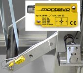
Inclinometer

I like these for a swing arm dancer
Or laser for a vertical type
This one is probably a Banner

inclinsensor.jpg
 
Originally posted by PLC:

This one is probably a Banner

Close. Its marketed as a Turck. Always hard to tell between banner and Turck though.

We use a slew of these as well (the Turck labeling, that is). Fairly low cost , reasonably robust and easy to use. Because of their measurement methodology they can be a little sensitive to vibrations especially in the low angle models (+/-5 degrees). But I definitely like these.

Keith
 
Wow. Just looked one up and this thing is over a grand with a conditioner.
Very interesting device. Never had one in my hands though.

HG Schaevitz sells LVIT's that don't require a conditioner, straight 4-20mA output. They also have traditional LVDT's that do require them. Prices are reasonable, they work decent IME but I'm not pushing them to their limits.

I see AD sells them now, looks like their pricing is lower than others. But you can grab this PN and find them at some of the big supply places or buy direct.
LRI19-150r-00-20A
 
Last edited:
THANKS.
There seems to be variety of these devices. Clearly this looks attractive for a device of choice for accurate speed refining. Yet still the man needs a roller encoder to get the unwinder diameter measurement. I have seen plenty of these and all of them look kind of like this one:
https://www.amazon.com/Polyurethane-Position-Measuring-Mounting-1000PPR200mm/dp/B07H29YBG9

He would just need to move the roll by less than half of rotation of the above roller to get an accurate reading of the unwinder diameter. I wouldn't be surprised to get an accurate result in like 1/10 of its rotation.
 

Similar Topics

Hello Folks, This is the design idea of a hydrogel coater that I am working on. Unwind>>Coat hydrogel>>Rewind Spces: 300mm wide web. 6000mm...
Replies
13
Views
4,357
Hi, I am working on printing inspection machine where 3 nos. ACS550 of smaller rating less than 7.5Kw on unwinder, main motor and rewinder but...
Replies
6
Views
2,952
Hello guys, I am trying with diferents ways for compute the actual diameter of steel strip that is unwinding and winding. I see there are many...
Replies
3
Views
1,757
Hello All, on my aplication 1-from siemen plc with aif setpoint send lenze drive with torque control value:-10% 2-send speed limitation -5%...
Replies
5
Views
2,585
I need some suggestion for calculations for an intermittent unwinder. The system consists of a servo controlled nip roller that moves film to a...
Replies
7
Views
3,620
Back
Top Bottom