phase shifting

adam_lhadi

Member
Join Date
Feb 2022
Location
algeria
Posts
59
Why encremental encoder have a phase shift of 90°between A,B phases ,if it's 60° 30° what happen what's the difference ,can we change the 90°in TIA PORTAL
 
90 degree offset between A and B channels means that the time between each event (rising A, rising B, falling A, falling B, rising A, etc) is the same for any given speed. Thus each event represents the same distance traveled if that's what you're measuring.
Why would you want it to be anything other than 90 degrees? In that case you would have to derate the maximum speed the decoder could handle based on the shortest time between events.
If there are ten mS between events at 90 degrees offset, channel A rises at 0 mS, channel B rises at 10 mS, channel A falls at 20 mS, and channel B falls at 30 mS, consistent 10 mS between events.
If the channels are offset by 60 degrees instead of 90, channel A rises at 0 mS, channel B rises at 6.6667 mS instead of at 10 mS, channel A still falls at 20 mS, channel B falls at 26.6667 mS instead of at 30 mS, so there are 6.6667 mS between some events and 13.3333 mS between others.
 
Why encremental encoder have a phase shift of 90°between A,B phases ,if it's 60° 30° what happen what's the difference ,can we change the 90°in TIA PORTAL


incremental encoders have their sensors (optical or whatever) offset by 90 d trees to to enable determination of direction. Those 90 degrees are time units. I made my first incremental encoder and posioned two optical sensors sort of 90 degree apart by eye and it worked, so the don't have to be exactly 90 but there will be a range within which code can determine which edge occured before which.


No you can not change that in any IDE nor is there any reason to

You may be confusing that with the options you have when configuring you HSC for your encoder, of that is the case the software just want to know what your encoder is or how you want to use it.
Now what are you trying to do?


typed on my phone
 
You may also find it informative or educational to create and encoder simulator in you software, you may use cyclic interrupt. I did that once for testing my code when I did not have the physical encoder. Not perfect but does the job.
 
90 degree offset between A and B channels means that the time between each event (rising A, rising B, falling A, falling B, rising A, etc) is the same for any given speed. Thus each event represents the same distance traveled if that's what you're measuring.
Why would you want it to be anything other than 90 degrees? In that case you would have to derate the maximum speed the decoder could handle based on the shortest time between events.
If there are ten mS between events at 90 degrees offset, channel A rises at 0 mS, channel B rises at 10 mS, channel A falls at 20 mS, and channel B falls at 30 mS, consistent 10 mS between events.
If the channels are offset by 60 degrees instead of 90, channel A rises at 0 mS, channel B rises at 6.6667 mS instead of at 10 mS, channel A still falls at 20 mS, channel B falls at 26.6667 mS instead of at 30 mS, so there are 6.6667 mS between some events and 13.3333 mS between others.
Hi bro
am working on a machine that basically cuts a metal coil to desired pieces
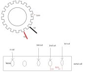
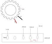
the machine have a rotating pinion with two sensors as in picture those sensor never have the same state like 0.0 or 1.1,whene you cut in the middle of the hole the next cut will always be in the middle of the next hole as long as you give positive integer number 1 2 3 4 5.....20.21.....
i have changed this mechanism with an encoder , the distances are equal and as desired but it does not repeat the same cutting position not always in the middle of the holes
the position of s2 is adjustable

machine.jpg
 
You may also find it informative or educational to create and encoder simulator in you software, you may use cyclic interrupt. I did that once for testing my code when I did not have the physical encoder. Not perfect but does the job.

Hi bro
am working on a machine that basically cuts a metal coil to desired pieces
the machine have a rotating pinion with two sensors as in picture those sensor never have the same state like 0.0 or 1.1,whene you cut in the middle of the hole the next cut will always be in the middle of the next hole as long as you give positive integer number 1 2 3 4 5.....20.21.....
i have changed this mechanism with an encoder , the distances are equal and as desired but it does not repeat the same cutting position not always in the middle of the holes
the position of s2 is adjustable

machine.jpg
 
First off I really want to know the brand of encoder you have that has that adjustable sensor, that is cool.


The basics of your application are always the same and it is a very common one.
Connect your encoder to your hardware and configure HSC for the highest possible resolution. Leave the sensors 90 degrees apart and configure HSC for AB quadrature.
We will assume some sort of trigger to start the process.
Now we have two options:
If th distances between the holes are exactly the same and repeat then you configure a cyclic counter that keeps resetting after each hole or sets of holes dependong on the application.
If the distance differs then do not reset the counter at all and let roll over. This solution works for the first case two, meaning it would work even when the distances are the same.
For both cases you need to use a hardware interrupt event when the counter value reached, the counter value equivalent to the distance where you want to cut. No conversion to distance back and forth just determine howanybpulsea between holes and every time the counter reaches that count it would fire a hardware interrupt the would initiate the cutting.


So when the process is triggered the counter value is acquired.
TargetCounterValue=CurrentCounterValue + DistanceToHoleCounterValur


typed again on my phone
 
the machine have a rotating pinion with two sensors as in picture those sensor never have the same state like 0.0 or 1.1,

That means the only or possible simultaneous states of sensors S1 and S2 at any single time* are

  • EITHER {S1:0;S2:1}
  • OR {S1:1,S2:2}
Is that correct?

* i.e. during any single PLC scan

whene you cut in the middle of the hole the next cut will always be in the middle of the next hole as long as you give positive integer number 1 2 3 4 5.....20.21.....

I do not understand what is meant here. How did we get from the state of two binary sensors to integers?
 
Last edited:
Also, you talk about cutting a metal coil into pieces, but then you talk about holes in the coil.

Is this a strip of material that is being cut into pieces, or is it a strip of material that is having holes drilled (or punched) into it, or perhaps both?

What do the S1 and S2 sensors detect? Is is the presence (1) or absense (0) of an tooth on the pinion in the the sensor's detection area?
 
Last edited:
I think I understand the application more.
That image is what used to be there and has been replaced with an incremental encoder.
So those switches have no relevance.
The machine cuts the plate exactly in the middle of each hole, or I should say it is required to do so.
And I think the holes are spaced evenly, so the plate must be prepunched.
There has to be a trigger that initiates the process and the distance from that trigger to the first hole must be know, after that it is pretty standard.


One more edit: and if the old setup had two switches that was probably to allow for an unequal distance between the holes. First hole cuts, them two cm later the other one. But the picture implies that they are evenly spaced so the second switch was not needed.


And yet another edit: now I am thinking the two switches were for precision, to fine tune the position with one switch.
 
Last edited:
Here is an archived project with TIA v16
It is untested and deals strictly with positioning using incremental encoder, HSC, Trigger sensor.
 
Changing the phase will not help and I haven't seen an encoder that allows changing the phase. On top of that it is not desirable because then it is hard to estimate the speed by the rate of change of the counts.


Instead of 20 counts per revolution try 20,000+. This should be easy to obtain pretty fine position resolution. A 10K PPR encoder should be able to produce 40K counts per revolution. The next problem is keeping the counts from drifting. Every once in a while the encoder must be homed or some way of making sure the the count where the cut should be made does not drift relative to the hole.


Do the metal stop for each cut or is the cutting done on-the-fly.
 
I think I understand the application more.
That image is what used to be there and has been replaced with an incremental encoder.
So those switches have no relevance.
The machine cuts the plate exactly in the middle of each hole, or I should say it is required to do so.
And I think the holes are spaced evenly, so the plate must be prepunched.
There has to be a trigger that initiates the process and the distance from that trigger to the first hole must be know, after that it is pretty standard.


One more edit: and if the old setup had two switches that was probably to allow for an unequal distance between the holes. First hole cuts, them two cm later the other one. But the picture implies that they are evenly spaced so the second switch was not needed.


And yet another edit: now I am thinking the two switches were for precision, to fine tune the position with one switch.
Hi Bro
in the old system when s1=1 means that the cutter blade is in the middle of the hole, also and somehow s1 is included in the measurement cause when removing one of the sensors you won't get a good results
what burns my mind is when i do the first cut manually in the middle of the hole then i give a cutting distance as an input (eg 10cm) starting from the middle of the previously cutted hole as the start of counting
the length of the cutted pieace is 10cm (-/+2mm) but the cut is not in the middle of the the hole even that the distance between hole is 1cm
the holes width is 5mm
if the cutt is not exacly in the middle that is exactable (just cut the hole between its width)) and that's what am not gatting
 

Similar Topics

What would happen if you ran a 60Hz Single Phase Motor on 50Hz supply?
Replies
6
Views
514
Hi all, I am having a problem with a powerflex 753 we have on site and keep getting input phase loss. The drive has been running for a long...
Replies
7
Views
1,334
We have an existing VSD where a three phase circuit breaker feeds the drive, and two phases also tee off to a contactor, which is energised to...
Replies
12
Views
1,471
Hello all... I'm looking for a 480v 3ø 25+ amp Solid State Relay to replace a mechanical one beating itself to death keeping temp in a heating...
Replies
15
Views
1,942
Hello. We have a Powerflex 700s phase II firmware 4.002, but the encoder card is burned. We want to disable it to use the Drive without motion...
Replies
0
Views
450
Back
Top Bottom