Non-retentive SET and RESET coil basic question...

I shoot of an email to the customer and their I&E contract company who did write the code telling them they may want to take a look at this and I'll be fine.
Well done. Everyone who knows and everyone who ought to have known beats responsibility to take action. And that's the most anyone could ask of you.

I was in a situation where code was clearly violated and there was risk to people and property so I chose to contact only the contractor and requested they send me a letter stating that they have been informed and that they will take the necessary steps. I made it clear that if I do not get that confirmation I would have an obligation to inform the customer. A few days later I got a letter from their lawyer and of course I informed the customer. A couple of years later the exact situation happened again on another site so I was way more careful in my approach and wording but that didn't help either and long story short I informed the customer and we are likely to be tied up in court of liable (defamation) for the next few years.
 
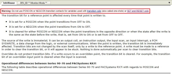
I've found the Proficy/PAC HELP files to be really easy to use and understand. Here's a good example...F1 and there you have it.

In this logic, the only affect it is having is holding the SET coil high and not allowing the RESET coil to toggle.

My written suggestion is to modify the logic to clear the transition reference bit before starting the 2-sec RESET timer.

Thanks again for all the input.

Transition contacts and and transition coils.png
 
With you there.

I guess the key question is, what is the behavior of the output rung of the TMR instruction?

  • If the TMR output rung is the timer .Q (timer expiry)
    • similar to say Siemens TIA portal,
    • then we will see this odd behavior where the Q00231 is not reset unless one of the one-shot inputs (%M04126 or %M4129) remains 1 for 2s.
  • If the TMR output rung is the timer .EN (timer enabled; mirror of input rung),
    • similar to say Rockwell RSLogix,
    • then the TMR .Q, if used elsewhere, is essentially a debounce of the inputs,
    • although there is still odd behavior: the Q00231 bit will immediately reset i.e. on the same scan it was set. So what is the purpose of Q00231 in that case?


The behavior of the output rung is the former i.e. .Q (timer expiry) like Siemens, so the output Q00231 will not be reset if at least one of the outputs is not 1 continuously for 2s after the rising edge of either.

This has the scent of a coder who either wanted to do summat really subtle and nuanced and perhaps clever yet did not think it necessary to comment exactly what that was, or did not understand ladder logic very well. If the latter, I wonder if they ever posted a query to this forum ...

drbitboy,

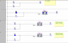
What makes you think it is the former? I just watched the logic execute and when either transition contact input is triggered on Rung 351, Q00231 will SET. Then the same input on Rung 352 will energize...BUT after the 2 second ON-Delay timer expires the RESET on Rung 352 will not energize which makes me think something is holding the Q00231 SET.

One-shot Set and Reset.jpg
 
When you watch that behavior, was the value in %R3292 continuing to increase? As long as the upper left node of a timer instruction is true, the timer will continue to accumulate time up to 32767. When the upper left node evaluates false, the TMR_TENTHS instruction will reset to zero. The upper right node evaluates true whenever the value in %R3292 is greater than or equal to the value at the PV node.
Have you checked to see if %Q00231 is used anywhere else in the program? Also are there any rungs manipulating the value in %R3292?
And finally, timers in a 90-30 consume three consecutive %R addresses. In your case the timer on rung 352 uses %R3292, %R3293, and %R3294. If any of those addresses are written to somewhere else in the program it will have an impact on the performance of the TMR instruction. A common mistake would be to address another time at %R3293. That mistake is particularly nasty because as long as only one of the timer instructions with the overlapping addresses is accumulating time at any particular point of your machine's operation, the timers will work just fine. But if the two are accumulating simultaneously, you will not observe the expected behavior. That means you can get away with the mistake for a long time before it bites you.
 
drbitboy,

What makes you think it is the former?

This: https://www.youtube.com/watch?v=HEGOlx9N9pI&t=279s

I just watched the logic execute and when either transition contact input is triggered on Rung 351, Q00231 will SET. Then the same input on Rung 352 will energize...BUT after the 2 second ON-Delay timer expires the RESET on Rung 352 will not energize which makes me think something is holding the Q00231 SET.

I don't know why that reset does not appear to execute when the timer expires, but then we see only a couple of rungs of that program.

I suspect Q00231 is being RESET there after the timer expires on that rung, but as you say, there may be something else, later in the program, returning Q00231 to the SET state.

Without the code and a proper test setup, there are limitations to what forum denizens can diagnose.

@Steve Bailey mentions some possibilities. The one thing I can tell you is that that a properly functioning PLC cares not a whit what you want it to do or think it will do, but it will mercilessly and inexorably do exactly what you told it to do according to its firmware and programming.
 
Last edited:
BUT after the 2 second ON-Delay timer expires the RESET on Rung 352
attachment.php

In the picture above, which appears to be the live status of the running program, the timer is not expired, but has been reset by the input contacts returning to false. And although that does not necessarily mean it did not expire (double negative), Q00231 is 1, so the most likely scenario is that

  1. one or both of the input contacts had a rising edge (0-to-1 transition), which SET Q00231 to 1 on rung 351, and
  2. both input contacts were or became 0 before 2s i.e. before the timer expired, so the RESET instruction was never triggered, leaving Q00231 with a value of 1.
It's not so much that Q00231 is being held at 1, more that, once Q00231 becomes 1, there are no instructions programmed and triggered that will reset Q00231 to 0.
 
I want to make sure that everyone understands that in the screenshot the highlighted -(R)- instruction on rung 352 indicates that %Q00231 is off (False). The -(S)- instruction is highlighted when when the bit is on (True). The -(R)- instruction is highlighted when the bit is off (False).
 
I want to make sure that everyone understands that in the screenshot the highlighted -(R)- instruction on rung 352 indicates that %Q00231 is off (False). The -(S)- instruction is highlighted when when the bit is on (True). The -(R)- instruction is highlighted when the bit is off (False).


I noticed but personally like the A-B way of highlighting BOTH when true.
 
Assuming the Timer is a delay on then either of the two bools set the output
This resets the output after the time so essentially it is a pulse for 2 seconds
If that input bool switches off before the timer is up then it never resets the output.
If the logic that sets the output was not pulse contacts it still works the same, the only difference is that on the first rung it will be set & reset on the next rung so as long as there is no logic using that output between the two it effectively work the same. So in effect it is a TP type timer i.e. pulse timer.
perhaps there is no TP timer in this PLC ?.

Pulse.png
 
I want to make sure that everyone understands that in the screenshot the highlighted -(R)- instruction on rung 352 indicates that %Q00231 is off (False). The -(S)- instruction is highlighted when when the bit is on (True). The -(R)- instruction is highlighted when the bit is off (False).


Whoops! Thanks, ignore parts of my last post where I went to the zoo.
 
Just to clarify and close out the subject...

Rung 351 one-shot sets the coil (shunt-trips a breaker)

Rung 352 resets the shunt-trip lockout and allows the user to turn the breaker back on.

The problem ended up being when rung 351 was energized, the building power was shunt-tripped. This ALSO shunt-tripped the AB 1100 which was initiating the one-shots on Rung 351.

The input was not held closed for the two seconds required to reset the shunt-trip lockout in Rung 352.

Solution, without modifying the logic, was to add a small DIN rail UPS (Weidmuller 12aH) to the AB 1100 to keep it powered up for the timer on Rung 352 to complete.

Thanks for everyone's input!
 
Last edited:
So, an exception to the rule that if something has been working for a long time, a sudden problem is probably not due to a fault in the program. In this case, the problem has been lurking for a long time.

Yep. Actually misunderstanding by the personnel on how the power shutdown on this building actually worked to begin with. The misunderstanding goes quite a way back, but only because of a recent fault with an I/O device did it actually draw their attention and their unfamiliarity with it was brought to light.

Anyway, taken care of now, and they have a better understanding of a component of their system.

Thanks again to everyone for their input and patience.
 
So, an exception to the rule that if something has been working for a long time, a sudden problem is probably not due to a fault in the program. In this case, the problem has been lurking for a long time.


I actually thought that rule was "Due to the program changing itself"


I have come across programming errors that took years to pop up like this.
 

Similar Topics

Been a long time since I've posted, but here we go. Started a new role in august and progressively learning about Codesys programming in...
Replies
2
Views
1,144
Hello guys, I am currently looking through some examples of how timers work, but this ladder logic diagram gets me really confused. Once I:1/0 is...
Replies
2
Views
1,837
I have a question about the TOFR instruction, a non-retentive timer that accumulates when the input bit goes low. For me this is in Rockwell's...
Replies
7
Views
3,687
Hi All I have tried to use the following code to reset a tmr. if Cycle.St & not(CycleStart_Rst) then Tmr_Main.Reset [:=] 1; CycleStart_Rst...
Replies
4
Views
3,669
I am using some MCR pairs in RSLogix 500 as if they were subroutines. I could, for example, have used JMP & LBL instruction pairs instead. When...
Replies
9
Views
6,144
Back
Top Bottom