Micrologix 1400 Messaging

Old No. 7

Member
Join Date
Jun 2010
Location
Ohio
Posts
173
I know there have been several posts on this subject but...

Is there a best practice for setting up multiple messages in a Micrologix 1400? I've seen it done several ways and most of the AB examples just show a single message.

My main question is timing and proper cascading. Do the MSG instructions just need to stay true for a scan for them to execute properly? Is there a downside if they are true for multiple scans? If you daisy cascade them with the DN bits what is the best way to reset the first MSG? Unlatching the EN bit?
 
The more scans they are true the more ethernet traffic there is.

Why multiple messages? One is simpler. You can send more than just a single item per message. I have a about 50 ints sent with one message, You can send bools through ints just having the originating PLC set the int to 0/1 for false/true. receiver can use a EQU block vs a XIC/XIO or you can have a little logic rung to set a binary bit to 0/1 off a EQU.

Each message also needs its own Control elements, eating more processor memory.
 
Some of the messages are doing multiple words. There are separate messages for reads and writes and there are multiple devices (PLCs and VFDs).
 
Some of the messages are doing multiple words. There are separate messages for reads and writes and there are multiple devices (PLCs and VFDs).

yea time them to reduce ethernet traffic. unless your timing is critical a second or two should be fine. I wouldn't cascade the messages but you could cascade timers to keep things organized.
 
Do the MSG instructions just need to stay true for a scan for them to execute properly? Is there a downside if they are true for multiple scans?

In all Rockwell controller operating systems, MSG instructions are executed just once each time the rung conditions transition from false to true. The number of scans that they rung conditions stay true doesn't matter.

You can find old or inappropriate examples of messaging logic (some of it in RA user manuals !) especially those that follow the old SLC-5/02 operating system method of using an unconditional rung for the MSG and toggling the Enable bit to zero as a method of executing the instruction. I don't recommend that method for any modern controllers.

My rule is to never use program logic to manipulate the control or status bits except for the .TO bit.

When you set .TO = 1, it causes a Timeout error exactly the same as if an actual timeout had occurred. The .ER bit is turned on, and the .ERR and .EXERR codes are the same as an ordinary timeout.

So that's Answer 1: set the rung true just once every time you want to trigger the MSG instruction.

What's the "best" way to handle periodic and sequential messaging ? That's a longer commentary thread.

It seems like if you only have a couple messages, you can probably get by with about any method. I've seen tons of examples of logic that don't feel right but when everything is working, they probably work just fine.

I setup a test with a couple ML1400 PLC's. PLC 1 has 8 messages reading and writing to PLC 2. The logic has an timer to start the messaging every 500ms and an index counter that starts the first message and when it is done (or errors out) it increments the counter and goes to the next message, and so on. Once the last message is done it resets the counter and starts over with the timer. You can watch the counter scan through all 8 messages in fractions of a second.

There is also another routine in PLC 1 that is trying to message the VFD's (which are not hooked up). When this routine is enabled those 20 messages fail (obviously) but it also causes the PLC messaging above to grind to a halt. Each message probably takes ~30 seconds and many of them error out. I'm assuming the failing VFD messages are clogging up the message que and causing the "good" messages to error out also.

Having comms for one device is bad enough, but having that knock out the rest of the device comms causes a real mess.

If you have suggestions for the best way to setup the logic, I'm all ears.
 
I don't have a master example program that will suit all purposes.

But I can show you some mistakes I've seen (and made !).

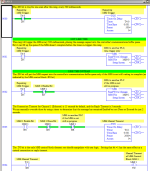
Below is the simplest one: using a self-resetting timer to periodically trigger a MSG instruction.

But what if the target device gets disconnected or doesn't answer before the timer repeats ? If you use only the timer's .DN bit, then the timer just keeps triggering new MSG commands to enter the execution queue.

How big that buffer or execution queue is depends on the controller.

So whenever you use a timer to trigger a MSG, also include (the inverse of) the .EN bit as a condition so that you don't re-trigger a message that is still enabled from the previous trigger.

MSG_Example_1.PNG
 
I don't have a master example program that will suit all purposes.

But I can show you some mistakes I've seen (and made !).

Below is the simplest one: using a self-resetting timer to periodically trigger a MSG instruction.

But what if the target device gets disconnected or doesn't answer before the timer repeats ? If you use only the timer's .DN bit, then the timer just keeps triggering new MSG commands to enter the execution queue.

How big that buffer or execution queue is depends on the controller.

So whenever you use a timer to trigger a MSG, also include (the inverse of) the .EN bit as a condition so that you don't re-trigger a message that is still enabled from the previous trigger.

THIS RIGHT HERE!!!!! (I did this on a Control Logix)

I learned not to interrupt an MSG, the hard way.

Worked great with 100mS timer until the plant started up and the network was flooded with traffic.... then not so much.

I was sweating bullets until I finally realized what I had done. Then I felt relieved but also really dumb.
 
Ken, this makes sense but a couple questions:

Do you use this same setup for multiple devices/messages? So each message gets its own trigger timer and timeout timer?

With multiple messages, do you stage/cascade them at all? Or just let them all occur when each timer happens and let the message queue sort it all out?

I'm guessing there's a good reason you don't do this, but could you shorten the channel timeouts instead of giving each message an external timout timer?
 
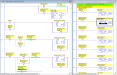
Here's a screenshot of how I do this. I am normally dealing with the serial port and radio modems, but the same method applies to CH1. One thing not shown is where I manipulate the MSGx:y.MTO value to set the timeout value for what I want it to be. I do that on 1st scan for all the MSG elements I will need, and it is typically set between 2 and 4 seconds even for radio modems. This, to me, is simpler than writing your own timeout TON and setting the MSGx:y.TO bit especially if you have a dozen or more messages in a program.

I use a FLL instruction to clear all the bits for each transition and set only the next bit I want. I also include separate bits to enable/disable each remote station, so I can include spares at design time and just skip over them. It also makes it handy if those enable bits are tied to an HMI so that in the event of a long term outage, you can turn off stations to keep the remaining working stations over all poll cycle short.

You cannot edit MSG rungs online in a Micrologix so it is handy to have all the things you think you'll need already programmed in for systems where expansion is likely and downtime is troublesome.

msg states.png
 
Last edited:
Ken, I tried your method for a couple of PLC read and writes. It seems to work well when I have individual timers for each read and write.

I tried using a single trigger and got some unexpected results. I set it up like your example but used the DN bit (or ER bit) from the first MSG to start the second MSG. What seems odd is that the second message seems to work ok, but the first message gets stuck where it appears to always be DN but the read doesn't actually work.

Do you always use individual trigger timers for all the messages? This seems like it wouldn't be ideal if you have a bunch of messages.
 
I use a polling timer that starts the poll cycle.

The first station is called to MSG and the .TO for that (and every) MSG is set to 3 seconds.

The next station is initiated by the DN or ER bits of the previous MSG. (max of 3 seconds)

When I reach the last remote and all have been polled or failed, I start a delay timer before starting all over again to allow the master polling radio time to cool.

I have a couple paths I take to the end points so each path has its own poling cycle and
each runs independently.

Some sites are more important and have 2 radios, if one fails the second is attempted by the ER bit of the first.

I also have diagnostic data in these to monitor how log they take to complete their task.
 
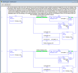
I use AB's suggested programming to trigger multiple messages. I've attached a screenshot to show how it works, the only issues I've run into with it is when one of the target PLCs is taken offline. The program assumes that all of the remote/target PLCs will stay online, otherwise the message sequence gets held up a corresponding amount of time to the number of MSGs directed to that PLC multiplied by the duration of the TimerTO timer around each MSG instruction. This is actually a screenshot from an old revision of my program, the 3000 has been lowered to 250. The program has 34 MSG instructions total, and the entire sequence of messages executes 4 times in just under a second according to a trend I made of the "Message_index" tag. At the end you would just MOV a 0 into Message_index after the final MSG instruction executes.

Obviously this is in a Logix environment, but I adapted it from a PLC-5 program that used N integer files in place of the Message_index and Disable_Message_bits tags.

MessageControl.PNG
 
Last edited:

Similar Topics

Hello everyone, I'm having an issue trying to get a messaging instruction to work. I'm trying to get some data from a Micrologix 1400 to a L83E...
Replies
18
Views
6,177
Hello all. I am working on a program that is using a Micrologix 1400 communicating with a Keyence SR-1000 barcode scanner over ethernet...
Replies
3
Views
2,292
Hi all, I am developing an application at the minute using a Kinetix 300 and a Micrologix 1400. The servo must follow a shaft on an existing...
Replies
11
Views
10,057
I have a Micrologix 1400 that needs to read & write a few integers & reals to three SLC5/04's that are connected via DH+ network. To bridge the...
Replies
4
Views
8,226
I am new to using the messaging system on this PLC. I have successfully connected 2 of them and used the Msg Read and Msg Write to exchange data...
Replies
2
Views
2,740
Back
Top Bottom