You are using an out of date browser. It may not display this or other websites correctly.
You should upgrade or use an alternative browser.
You should upgrade or use an alternative browser.
Help with studio 5000
- Thread starter Baconcrunchwrap
- Start date
Robb B
Lifetime Supporting Member
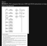
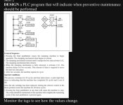
Homework assignment? A real world scenario, I'd use a mapped input and output file. Sometimes I find it helpful to take the process details down into individual steps. For example, your first picture, step 1, You'll need logic that starts the cylinder, reaches the limit switch presumably, stops and retracts, then repeats. Sometimes you will have to rework a previous step if other conditions present themselves; errors, overloads, etc. Start by drawing it out on paper, this usually helps me to find where I'm missing steps or conditions.
I'm not sure where the ADD and SUB are supposed to count from, maybe each cycle of a press? Though that doesn't guarantee a product, would need something that proves the object left the press, like a photo-eye or proximity switch.
I'm not sure where the ADD and SUB are supposed to count from, maybe each cycle of a press? Though that doesn't guarantee a product, would need something that proves the object left the press, like a photo-eye or proximity switch.
Steve Bailey
Lifetime Supporting Member + Moderator
Welcome to the forum. Please demonstrate some effort on your part by posting what you have already done, or at least what you think you need to do. If someone here does your homework for you, all you've learned is that occasionally you can find answers on the internet.
Baconcrunchwrap
Member
OP
Steve Bailey
Lifetime Supporting Member + Moderator
Really?
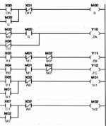
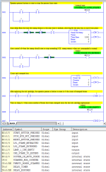
The jpg for the PM task shows 5 inputs and two outputs. Your attempt at a solution shows eight inputs and three outputs. The task calls for a time delay but I don't see any timer in your attempt. The names associated with the I/O points don't match the task description. The task description uses Allen Bradley naming conventions while your example looks like Mitsubishi.
You need rung comments to explain what you think each rung of logic is supposed to do.
I think other replies here are correct, to give you a bit of a start I suggest you get a sheet of paper & think about the sequence of events, from there you should be able to put some code together.
Without actually showing you code here is a way of doing it.
Assume PLC is first powered up, & it is not in auto run.
So the first thing is the auto start latch (seal in circuit).
The logic needs the following:
The start button is pressed. and providing the count is less than 20 (i.e. a compare) and the stop button is on (N/C & not pressed) then it outputs the internal memory bit "Auto Run", this is ORED with the start button to seal it in.
Explanation: you need to drop out the auto if stop button pressed or the count = 20 (Counter.DN bit).
Then the solenoid that extends the stamp logic:
If we are in Auto Run, AND NOT Stamp Extended, out the stamp solenoid
Then we need to retract it:
If in auto AND the stamp is extended, Retract it.
Then we need to count the number of stamps:
Increment the count.
After the counter reaches 20 then the auto drops out.
A reset operation on the reset switch resets the count and allow the system to re-start.
This takes 5 rungs of simple code.
Rung 1 Auto Stop/Start latch
Rung 2 Extend stamp
Rung 3 Retract Stamp (memory bit as only single acting solenoid)
Rung 4 Counter
Rung 5 Ink out lamp
I think you need to take each item in the original problem and break it down into pseudo-code. (https://www.geeksforgeeks.org/how-to-write-a-pseudo-code/ ) then once you have the pseudo-code try and work each section into a workable bit of ladder code.
If you break the problem down as @Parky says the steps should become easy to code. Then we can help with the polishing.
If you break the problem down as @Parky says the steps should become easy to code. Then we can help with the polishing.
Yet another poorly thought out excercise from some institution, notice the bad part count is a pushbutton, how do you know when to press the button, this is truly a bad implementation, at the very least, there would be perhaps some sort of testing of parts i.e. a signal from some sort of detector or at the very least a sensor of some sort, I admit that for the purpose of excercise the use of a pushbutton to simulate bad parts but at least should be explained the push button was inserted just for testing.
Perhaps start with the simpler example but do not use a counter use a Dinteger as the count so your code can be modified from the simpler stamp logic.
Perhaps start with the simpler example but do not use a counter use a Dinteger as the count so your code can be modified from the simpler stamp logic.
Baconcrunchwrap
Member
OP
drbitboy
Lifetime Supporting Member
@Baconcrunchwrap,
1) Programming PLCs is all about time sampled in discrete in scan cycles. On each scan cycle, the code
3) Almost all relay logic is based on just a few patterns; see this link, and memorize the following patterns:
4) All of those patterns are based on the Input Map (input => output) pattern. The key is understanding that, on any rung,
1) Programming PLCs is all about time sampled in discrete in scan cycles. On each scan cycle, the code
- detects when inputs change;
- remembers internal states from past scan cycles;
- remembers outputs from past scan cycles;
- updates the internal states, according to the logic of the program, on the current scan cycle for future scan cycles;
- updates the outputs, according to the logic of the program, on the current cycle.
3) Almost all relay logic is based on just a few patterns; see this link, and memorize the following patterns:
4) All of those patterns are based on the Input Map (input => output) pattern. The key is understanding that, on any rung,
- two or more instructions, or groups of instructions, in series (connected left-to-right on a rung or branch) are in a logical AND relationship, and
- two or more instructions, or groups of instructions, in parallel (two or more branches connected vertically at their ends) are in a logical OR relationship.
- So the canonical Start/Stop circuit (cf. here) is expressing the logic
- If either the Start or Run bits are 1, and the Stop button is not pressed, then assign 1 to the Run bitbox, else assign 0 to the Run bitbox.
- Or, more concisely
- Run = (Start OR Run) AND (NOT Stop)
Steve Bailey
Lifetime Supporting Member + Moderator
Ok, that's a start at following Parky's suggestion.
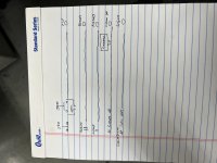
I don't see any coil (OTE) instruction for the "Latch" contact (XIC) in your first rung.
What does the "Run" coil in the first rung do?
What controls the "Extend" contact in the second rung?
What controls the "Retract" contact in the third rung?
What controls the "Count Up" contact in the fourth rung?
How is the counter reset after the operator changes the ink cartridge?
Are you sure you want a normally closed contact (XIO) in the last rung?
drbitboy
Lifetime Supporting Member
Could you please explainThis is what I’ve come up with
- Which of the two problems Skill 5 or Skill 2 this is supposed to address (I think it's Skill 2 because of the 20 preset in the counter)?
- What the logic on the last rung is doing i.e. what is the XIO (i.e. NC) instruction testing?
- Why the [Run] bitbox assigned on the first rung is not used anywhere else?
- How the values (1 or 0) in each of the bitboxes [Latch], [Extend], [Retract], and [Count Up] in the XIC (NO) instructions are assigned?
Last edited:
drbitboy
Lifetime Supporting Member
@Baconwrapcrunch,
Seriously, this forum contains a plethora of experience that has written programs similar if not identical to these dozens if not hundreds of times. These problems are trivial to that wealth of experience even if they are opaque to you, and that experience is more than willing to share.
But beware: mocking that experience with what could be a transparently minimal effort in an attempt to get a solution will not end well.
I did not enjoy writing that, but I feel it needed to be said.
And if your attempts were indeed genuine then I apologize as it only means you have a longer, though certainly navigable, path ahead.
With that out of the way, as a start, especially as it appears the ladder logic is beyond you at this point, please describe in prose what you are doing on each of those rungs.
Start with the last one, which should be the simplest of the entire program. I.e. what events or states cause the lamp L1 to be either on or off? Don't be concerned yet with how those events or states come to be or not to be, that is not the question ; just describe them in words.
Every long journey begins with a single step, and working backwards from there might be a workable path to the complete solution.
Seriously, this forum contains a plethora of experience that has written programs similar if not identical to these dozens if not hundreds of times. These problems are trivial to that wealth of experience even if they are opaque to you, and that experience is more than willing to share.
But beware: mocking that experience with what could be a transparently minimal effort in an attempt to get a solution will not end well.
I did not enjoy writing that, but I feel it needed to be said.
And if your attempts were indeed genuine then I apologize as it only means you have a longer, though certainly navigable, path ahead.
With that out of the way, as a start, especially as it appears the ladder logic is beyond you at this point, please describe in prose what you are doing on each of those rungs.
Start with the last one, which should be the simplest of the entire program. I.e. what events or states cause the lamp L1 to be either on or off? Don't be concerned yet with how those events or states come to be or not to be, that is not the question
Every long journey begins with a single step, and working backwards from there might be a workable path to the complete solution.
Last edited:
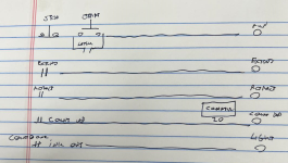
Although I feel I should not post this as it is too close to the code that is required, however, it is clear as in many cases, tutors in my experience from some of my apprentices experiences do not teach the fundamentals of PLC or logic & how to implement the code, I do feel it is a poor way of teaching perhaps they do not have the time (or cannot be bothered) in teaching the basics. It is too common for tutors to throw them a PLC & let them fumble their way through, that is if they are lucky enough to get their hands on one.
So attached, is my version of a print applicator, It is not in RSL & the I/O is just symbols so even though it is a working application will require the OP to think.
I have split it into extra rungs (I would normally integrate some of them) but as the IDE the OP will be using may not be able to integrate some of the rungs.
My original was only 5 rungs plus 2 temporary rungs for simulation.
Perhaps when the OP gets this one up & running then with some thought could add the extra code required for the second exercise.
Similar Topics
Please see attached file. I need this program in Function Block form but I am totally lost on this. Any help would be appreciated.
Thanks!
- Replies
- 8
- Views
- 291
does anyone know how to fix the icons on the tool bar they disappeared about a week ago this is on studio 5000 any help would be grate?
- Replies
- 7
- Views
- 1,891
Hello,
We are beginning to use the View Designer software for the newer Panelview 5500 and 5300 HMIs.
I one we are starting with is the 5300 10"...
- Replies
- 1
- Views
- 1,186
Hey everyone. I'm new to programming and am currently the only one who does any in my workplace. I have access to rs logix 500 pro, and ccw, but...
- Replies
- 6
- Views
- 2,019
Has anyone used the "MAJ" motion command? I'm trying to move an injector in the reverse direction. I would appreciate some help.
THanks.
- Replies
- 5
- Views
- 2,148


