![]() ![]() ![]() ![]() ![]() ![]() |
||
![]() |
||
![]() ![]() ![]() ![]() This board is for PLC Related Q&A ONLY. Please DON'T use it for advertising, etc. |
||
![]() |
![]() |
#46 |
Lifetime Supporting Member
|
The valve is not opening (i.e. passing flow) until CV% is around 24%; that is effectively a reset windup neither visible to, nor affected by, the anti-windup reset algorithm built in to the PID.
Try adding a constant feedforward (Control Word 6; N16:5 in your configuration) of ~3900 once the vent valve closes and/or the PID is switched to Automatic (.AM=0). _
__________________
_ Brian T. Carcich i) Take care of the bits, and the bytes will take care of themselves. ii) There is no software problem that cannot be solved with another layer of indirection. iii) Measurement is hard. iv) I solemnly swear that I am up to no good ![]() v) I probably have the highest ratio of forum posts to actual applications in the field (∞). vi) Hakuna matata. Last edited by drbitboy; November 1st, 2022 at 12:34 PM. |
![]() |
![]() |
#47 | |
Lifetime Supporting Member
![]() ![]() Join Date: Feb 2011
Location: BC, Canuckistan
Posts: 260
|
Quote:
|
|
![]() |
![]() |
#48 | |
Lifetime Supporting Member
|
Quote:
You do not have to be in manual first and then, at 75% of setpoint, (i) move the CV% to 25% and (2) switch to auto. That valve is closed when the CV+feedback* is between 0 and 24%**. Closed. Shut. Not open. Zero flow. That valve's controllable range is 24% to (maybe) 100% in CV%, or ~3900 to 16383 in CV. Spending any time between 0% and 24% is a waste of time and the primary reason for the overshoot***. So you can put it in Auto like you do now and write 3900 into Control Word 6 whenever it is in Auto e.g. If you do that, the valve, and the PV, will react more or less immediately when the PV crosses the SP. * the feedforward value in Control Word 6 is an INT in the range -16383 to +16383; a CV% of 24% open is ~3900 on that scale. ** 24% is my calibrated eyeball's estimate from the trend, it may be 23% or 25% *** Note that, at 165PSI setpoint, the pressure is rising slower because of lower pump flow into the system (centrifugal pump curve => increased head => less flow), and that slower rise in pressure is why it overshoots less i.e. it only rises 5PSI before CV reaches ~3900 and the valve actually first opens.
__________________
_ Brian T. Carcich i) Take care of the bits, and the bytes will take care of themselves. ii) There is no software problem that cannot be solved with another layer of indirection. iii) Measurement is hard. iv) I solemnly swear that I am up to no good ![]() v) I probably have the highest ratio of forum posts to actual applications in the field (∞). vi) Hakuna matata. Last edited by drbitboy; November 1st, 2022 at 02:58 PM. |
|
![]() |
![]() |
#49 |
Lifetime Supporting Member
|
@Peter Nachtwey did an interesting study for a valve that was not only non-linear, it was more or less stochastic; I forget if it was a sticky valve.
This situation is far simpler than that ...
__________________
_ Brian T. Carcich i) Take care of the bits, and the bytes will take care of themselves. ii) There is no software problem that cannot be solved with another layer of indirection. iii) Measurement is hard. iv) I solemnly swear that I am up to no good ![]() v) I probably have the highest ratio of forum posts to actual applications in the field (∞). vi) Hakuna matata. |
![]() |
![]() |
#50 |
Lifetime Supporting Member
|
What is the timescale on that trend plot?
Is it two minutes per division?
__________________
_ Brian T. Carcich i) Take care of the bits, and the bytes will take care of themselves. ii) There is no software problem that cannot be solved with another layer of indirection. iii) Measurement is hard. iv) I solemnly swear that I am up to no good ![]() v) I probably have the highest ratio of forum posts to actual applications in the field (∞). vi) Hakuna matata. Last edited by drbitboy; November 1st, 2022 at 11:55 PM. |
![]() |
![]() |
#51 | |
Member
![]() ![]() Join Date: Jul 2022
Location: FrozenHell
Posts: 79
|
Quote:
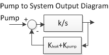
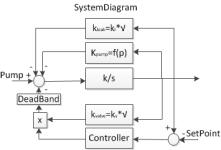
kleak - system leakage coefficient (~sqrt(system pressure)) kpump - pump efficiency reduction factor kvalve - coefficient of increase in the capacity of the control valve (~sqrt(system pressure)) You can define controller gains using system transfer function G(s) = (k/s)*exp(-deadtime*s) / (1 + k/s*exp(-deadtime*s) * (kleak + kpump + kvalve * (kp + ki/s))) I also gave a diagram from the Pump to the system output. Transfer function from the Pump to the system output is: G(s) = k / (T*s+1) T = 1 / (k*(kleak + kpump) k = 1 / (kleak + kpump) If we express the deadband as deadtime, then the transfer function from the controller output to the system output is: G(s) = k * exp(-DeadTime*s) / (T*s+1) T = 1 / (k*(kleak + kpump) k = kvalve / (kleak + kpump) The more pressure, the more kleak, kpump, kvalve, i.e. decreases T (for both TFs), the gain from the pump to the system outlet decreases more than CO to SO gain. That is why the control is more effective at high pressure. If we find CO to SO transfer function coefficients (using the curves from your post #41): G(s) = 0.91 * exp(-60*s) / (36*s+1) 60/36 = 1,6667 – it is NOT good In other words your ACTUAL PROBLEM IS A CONTROL VALVE DEADBAND The most efficient solution would be make control valve position=24% (or what the actual deadband) to controller output=0 as drbitboy wrote. This case you'll get easiest to control first order lag plant G(s) = 0.91/ (36*s+1) I think it would be safer to set the control valve position to 0 at the end of the cycle. Last edited by MaxK; November 2nd, 2022 at 07:28 AM. |
|
![]() |
![]() |
#52 |
Lifetime Supporting Member
|
Wow, noice.
I was going to say the pump curve was available in the trend plot, (positive dPressure/dt as a function of Pressure while the valve is closed; dPressure/dt is a proxy for pump flow dVolume/dt from rearranging the bulk modulus formula K = dP / (dV/V0), to first order anyway). And a similar approach for the valve would model negative dPressure/dt as a function of Pressure and CV% e.g. dPressure/dt = √P / (C (76/(CV%-24) + R) whenever CV% > 24, and zero otherwise (valve is closed). Adding those positive and negative dPressure/dt values yields a dynamic model of the pressure of the vessel as a function of CV%. Of course there are a lot of things not modeled (head from storage tank, non-linear valve characteristic, leakage, etc.).
__________________
_ Brian T. Carcich i) Take care of the bits, and the bytes will take care of themselves. ii) There is no software problem that cannot be solved with another layer of indirection. iii) Measurement is hard. iv) I solemnly swear that I am up to no good ![]() v) I probably have the highest ratio of forum posts to actual applications in the field (∞). vi) Hakuna matata. |
![]() |
![]() |
#53 |
Lifetime Supporting Member
|
@Robb B, I am curious about the end of the cycle, starting around 2:57 PM on the trend.
It looks like some other drain has been opened, or maybe the PID CV was disconnected from the control valve, because the pressure drops steeply. The PID is still trying to control so it closes (CV drops to zero). The setpoint is also being ramped down in steps, which seems superfluous if the control (of the?) valve is bypassed, but each step down in SP gives a positive kick to the CV - was there some Derivative action in place during that trend i.e. Td was non-zero?
__________________
_ Brian T. Carcich i) Take care of the bits, and the bytes will take care of themselves. ii) There is no software problem that cannot be solved with another layer of indirection. iii) Measurement is hard. iv) I solemnly swear that I am up to no good ![]() v) I probably have the highest ratio of forum posts to actual applications in the field (∞). vi) Hakuna matata. |
![]() |
![]() |
#54 | |
Lifetime Supporting Member
![]() ![]() Join Date: Feb 2011
Location: BC, Canuckistan
Posts: 260
|
Quote:
|
|
![]() |
![]() |
#55 | |
Lifetime Supporting Member
|
Quote:
I'm guessing the pump is stopped, which is the real reason the pressure drops (backflow through the pump?) like a stone. The control valve is trying to respond to the drop in pressure but not actually modulating anything at that point; the lowering of the setpoint is interesting but meaningless. The CV kicks at each setpoint drop are momentary; they could be caused by a non-zero Td, but Kc could also be the cause if Td was 0. Btw, instead of feed forward/bias, another way to bump the CV to 24% or so might be to put ~3900 in the Output Minimum, word 12 of the Control Block (N16:12).
__________________
_ Brian T. Carcich i) Take care of the bits, and the bytes will take care of themselves. ii) There is no software problem that cannot be solved with another layer of indirection. iii) Measurement is hard. iv) I solemnly swear that I am up to no good ![]() v) I probably have the highest ratio of forum posts to actual applications in the field (∞). vi) Hakuna matata. Last edited by drbitboy; November 2nd, 2022 at 11:37 AM. |
|
![]() |
![]() |
#56 | |
Lifetime Supporting Member
![]() ![]() Join Date: Feb 2011
Location: BC, Canuckistan
Posts: 260
|
Quote:
I tried using the MOV 3900 to word 6, and it shows in the PID setup box, but didn't have any effect on the Output percentage, ie: it didn't jump the output to ~24% even after crossing the setpoint. I tried tuning the PID using the suggested method in rockwells help manual on the PID instruction. I got oscillation around Kc of 25 so I halved that, then the oscillation period was about 20 seconds, so Ti is 0.3, and derivative should be 1/8 of the Ti, which came out to 0.0375 so I went with 0.04 because of limited decimals. Response at setpoint is very smooth, but I haven't had a chance to test it against the initial ramping time. |
|
![]() |
![]() |
#57 |
Lifetime Supporting Member
|
But that does nothing, because the pressure has already dropped, and the controller is trying to raise the pressure by closing the valve. Presumably another bleed valve has been opened, and if that is the case, then the code that ramps down the setpoint serves no purpose.
Huh. Maybe 3900 needs to be in word 12 (Output Minimum, CVL) instead, or as well, because without that, any feed forward bias in Word 6 is eventually overridden (negated) by the accumulation of reset (Ti) bias, and the CV output ends up at 0 anyway. What values are in Words 17 and 18 when Word 12 is 0 and Word 6 is 3900, and what values are in Words 17 and 18 when Words 12 and 6 are both 0?
__________________
_ Brian T. Carcich i) Take care of the bits, and the bytes will take care of themselves. ii) There is no software problem that cannot be solved with another layer of indirection. iii) Measurement is hard. iv) I solemnly swear that I am up to no good ![]() v) I probably have the highest ratio of forum posts to actual applications in the field (∞). vi) Hakuna matata. Last edited by drbitboy; November 2nd, 2022 at 04:40 PM. |
![]() |
![]() |
#58 |
Lifetime Supporting Member
|
off course you could, as an alternative, apply the bias external to the PID, i.e. leave the PID as is (Word 6 = 0 = Word 12), and add 3900 to the PID CV output (ADD N9:5 2900 Nx:y) after the PID whenever .EN is 1 and .AM is 0, and send that result (Nx:y) to your valve output.
__________________
_ Brian T. Carcich i) Take care of the bits, and the bytes will take care of themselves. ii) There is no software problem that cannot be solved with another layer of indirection. iii) Measurement is hard. iv) I solemnly swear that I am up to no good ![]() v) I probably have the highest ratio of forum posts to actual applications in the field (∞). vi) Hakuna matata. |
![]() |
![]() |
#59 | |
Member
![]() ![]() Join Date: Jul 2022
Location: FrozenHell
Posts: 79
|
Quote:
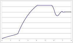
If setpoint changes then changes system pressure, i.e. changes system model (model acts some kind like spring). When it is rejecting disturbance it is possible to “hold” pressure, i.e. “freez” model. In summary, I think it makes sense to try more aggressive controller settings for disturbance rejecting . More aggressive controll will allow: 1. Faster overcome the deadband of the control valve 2. Stabilize the pressure in the system faster and prevent the system model from changing. Curve below illustrated my idea |
|
![]() |
![]() |
#60 | |
Lifetime Supporting Member
|
Quote:
Anti-reset windup is a feature that prevents the integral term from becomingSo the proposed lower limit ~3900 should be put into the Output Minimum - CVL at Word 12 (N16:12) to ensure the valve opens sooner. This may also change the tuning. The feed forward/bias in Word 6 is meant for process disturbances, i.e. time-dependent bias.
__________________
_ Brian T. Carcich i) Take care of the bits, and the bytes will take care of themselves. ii) There is no software problem that cannot be solved with another layer of indirection. iii) Measurement is hard. iv) I solemnly swear that I am up to no good ![]() v) I probably have the highest ratio of forum posts to actual applications in the field (∞). vi) Hakuna matata. Last edited by drbitboy; November 3rd, 2022 at 08:49 AM. |
|
![]() |
![]() |
Currently Active Users Viewing This Thread: 1 (0 members and 1 guests) | |
Thread Tools | |
Display Modes | |
|
|
![]() |
||||
Thread | Thread Starter | Forum | Replies | Last Post |
PID Position to Velocity Equation Tuning Parameter Conversion | JLand | LIVE PLC Questions And Answers | 7 | January 18th, 2022 06:15 PM |
SLC 5/05 Communication Problem with Serial Port.. | pranav.mistry003 | LIVE PLC Questions And Answers | 2 | August 23rd, 2012 04:41 PM |
Reading L32E with SLC 5/05 | 24fretslater | LIVE PLC Questions And Answers | 7 | February 23rd, 2012 12:26 PM |
Control Slc 5/04 PID | The Plc Kid | LIVE PLC Questions And Answers | 1 | August 6th, 2009 04:41 PM |
SLC 5/05 PID Time Mode Question | Dwarfer1 | LIVE PLC Questions And Answers | 7 | December 15th, 2004 05:52 AM |