PowerFlex 755 Dynamic Braking Monitoring

There is no parameter in the drive you can monitor to set the shortest decal time
To determine the best decal would be to look at the ON OFF ratio of the braking transistor but you will need a good scope for that
As was mentioned earlier a good option would be to install an external DBU Dynamic Breaking Unit (Buss Loader) or a Line Regenerative Module
Keep in mind rapid deceleration comes with it’s own set of problems. I saw an impeller spin off the motor shaft because of the reverse torque induced on short decal time. I had another machine strip gears in the machine because the decal rate was too short

As for the buss voltage of 630v while running as I stated it is bit low for a 480v ac line
You can run at that and in fact you are running at that level. My guess is that your line voltage is around 430 - 440 range that’s still within the operating range of the drive. (400V Class) In fact you could run it in a single phase supply if you wanted to run at a reduced HP rating this is done often.
I actually have a drive on my shelf that’s rated 120V Single phase input 240V 3PH out
It’s amazing what a modern VFD can do if setup correctly
The best thing is to read and understand the manuals
 
Take a look a this:

https://literature.rockwellautomation.com/idc/groups/literature/documents/rm/750-rm002_-en-p.pdf

starting at page 41. Pages 45 through 51 contain most of the good info. It looks like your bus regulation trigger voltage is in the 750VDC area. So it certainly looks like the drive is regulating bus voltage.

I guess I would check your bus regulation mode just to make sure it is set to dynamic Braking or at least DB 1st. Also, check the drive setting for regen power limit. I think the default is 50% rated power.

Other than that, as said before, keep decreasing your decel time until the resistor opens the thermal and you will be largely optomised.

Keith
 
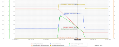
We've been doing some extensive testing with this and slowing decreasing our DECEL value to optimize stopping time. From the attached data log, you can see that the braking current peaks around 25A at the beginning of the decel and then slowly tapers down; meanwhile, the motor current goes up and is getting very close to the FLA of the motor (57.8A). We still have plenty of power left in the resistor bank (up to 39A / 13kW) but getting worried that we might be close to our limit with the motor FLA. Any tips or is my thought process correct here?

Untitled.png
 
It's absolutely controlling decel. In coast mode, it takes about 30 minutes to come to a stop. We are stopping it in 3 minutes with decel. The resistor bank, which was properly spec'd, gets warm during this period.

I just need to know which parameter we should be looking at while playing with the decel rates so we don't come near an overvoltage condition.

The 'gets warm' is a pretty good observation. If you dig a little more, you'll find that Rockwell recommends an overtemp device attached to the DB resistor, and interlocked with the DB contactor....lots of designers 'skip' this step.
If you specifically buy a resistor made for DB, it will have the thermal switch (old-timers like me still call them Klix-ons) attached on or very near the resistor, with free leads coming out to a terminal block for field wiring attachment.

Yep! We're past that part, fortunately.
 
Originally posted by phuz:

...but getting worried that we might be close to our limit with the motor FLA.

This isn't in and of itself that big a deal. Just like you rely on duty cycle to let you heat up the resistors during decel and then cool them down at all other times you can (possibly) do the same thing with the motor. It looks like you are idling along at just a little over magnetizing current during normal run. So the motor isn't generating all that much heat when you are just spinning. That means you have some extra thermal capacity in the motor to beat it harder on accel and decel.

The question is do you have enough drive to do this? Is the drive sized to provide an extended period over motor rated current. For example, if you have enough drive you could run the motor at 150% of rated current through the whole decel event. The motor would heat up some but not enough to be an issue. But the drive needs to be able to deliver that level of current for an extended period. If you have a 60HP normal duty drive connected to a 60HP motor you will likely not be able to take advantage of extended operation above motor rated current. The drive won't be able to deliver.

Keith
 

Similar Topics

I have a customer who has a centrifuge application. The plant engineer did all the calculations on the centrifuge to arrive at a WK^2 of 6458...
Replies
14
Views
3,553
So I have a sort of unique situation where I'm wanting to run a PF755 from the IO and over ethernet. Of course, this comes with it's own set of...
Replies
7
Views
59
Hi I was wondering I need to update the firmware of a 755 inverter does the drive hold the program on the drive and just updates the firmware or...
Replies
5
Views
110
So I'm replacing a terminal block on the inverter board for a 755. I'm wondering if anyone knows what conformal coating would be best? I'm not...
Replies
1
Views
106
Powerflex 755, running 2 weeks, and faulting with code 17 input phase loss.
Replies
3
Views
201
Back
Top Bottom