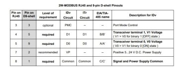
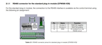
Is There a standard wiring for modbus RS485 RTU two wires ?

widelto

Member
Join Date
Jul 2005
Location
Barranquilla, Colombia
Posts
3,392
HI guys:
I am attaching several diagram from several sources, it seems to be that there is no such a wiring standard for modbus RS485 RTU.
In some cases A wire is (+) an in other cases A is (-), and the same for wire B, some vendors do not mention A or B but TX+ or TX-.

Why such differences exist ?

That makes non sense.

thanks,

widelto
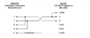
from rockwell.jpg from manual 6ES7541‑1AB00‑0AB0.jpg from bobtech.ro.jpg standard modbus.org.jpg
 
You are correct that no standard exists for the labeling of RS-485 data conductors, nor is there a standard for how the 0V reference is connected or described.

Why ? Why does the sun come up, or are the stars just pinholes in the curtain of night ?

Every time I connect a multi-vendor RS-485 system I simply try to read the documentation for each device carefully, and consider whether I should add an isolator. It's still a coin-flip about whether I get the data conductor assignments correct.

Ken , I am retired now, I used to be the boss , personally I never liked modbus RTU and never had the necessity to use it. The only advantage to me , it is the distance that can handle.

A new contract brought me out of retirement just to be aware of this mess , this is mi first project with modbus RTU.

From now on I will flip the coin as you recommend, thanks.
 
@Ken Roach: I am thinking out loud. That means that it only matters that (+) goes to (+) and (-) goes to (-), regardless if the labeling is A or B, or am I wrong ?.
 
I keep in my case both male and female DB9 breakout connectors in case I need it. Few weeks ago I had to connect "+" from the master to "-" to the slave and on slave there was DB9 connector.
 
@Ken Roach: I am thinking out loud. That means that it only matters that (+) goes to (+) and (-) goes to (-), regardless if the labeling is A or B, or am I wrong ?.

I am pretty sure this is correct.

I have not done any RS-485 with PLCs, only RS-232, but I did a fair bit in the broadcast industry (switchers, routers, and under-monitor displays). My experience is that nothing ever got fried if I got a wire into the wrong slot of an RJ connector, and I usually got away without a third wire for ground (a lot of the hardware manufacturers in broadcast are cheap).

BTW, there is a Something* Company how-to youtube video about getting data from a serial line into their PLCs. The first several minutes have a pretty detailed description of how serial/UARTs work, I think it was mainly focused on RS-232, but there may have been some good info about RS-485/-422.

* I think the name started with H. IIRC it was related someone trying to read barcodes in this forum at some point in the past year. I think there was some kind of semi-formal relationship between this company's PLC and GE PLCs, maybe some of the I/O card would work for both, but I am not sure.

Edit: Horner! Youtube here.


Edit2: RS-485 Wiki has some references too, but I suspect they will only add to confusion if they are not consistent.
 
Last edited:
The driver lines are defined, at least in the Modbus Spec (page 22)

https://modbus.org/docs/Modbus_over_serial_line_V1_02.pdf

The same Modbus spec calls for the 3rd-wire common/reference conductor, but again, implementation of such is almost rare.

That same spec calls out pinouts for RJ-45 connectors used for RS-485 Modbus RTU.\, as well as DB-9 pinouts (pages 29-31).

There's even recommnded color coding on page 32.

But there's no Modbus police, no Modbus prosecutor, nor Modbus Judge and jury, so vendors do as they like and sometimes different divisions of one common company will label the lines backwards of another division, and most do not even provide the 3rd wire reference terminal for 2-wire networks.
 
Thank you all for sharing your experiences , Brian : I like that video.
I am supposed to travel tomorrow to the site and promise to share my results.
My PLC is a S7-1500 (BTW my first aproach to Siemens after more than 32 years exclusively with Allen Bradley due to the company I used to work for) and IQT 3 actuators (9) from ROTORK.
 
3rd wire on 485

I agree with what has been said and I've done stuff with only two wires hooked up on 485 - but I tend to believe in hooking up the third wire if it is available. The line drivers and receivers are supposed to only transmit and respond to differential voltage but they are not perfect devices. If the common-mode voltage (to ground) is too high the chips may have trouble. This probably means a grounding problem that may or may not be fixed with the third wire. Whether the ends are 'isolated' factors into it. There's not a single answer for all situations.

It makes me wonder how we managed to run DH+ and RIO all over and not have more troubles than we did. Nowdays my answer is to use fiber whenever going outside or going a long way or across different building power feeds or I can get by with it without the owner asking questions. Electrical isolation beats suppression almost every time. Properly installed fiber seems to resist most things except backhoes.
 
YouTube just reminded me that I need to choose a channel "Handle", but my channel is from a very long time ago from before technical YouTubers like Kurt Braun or Tim Wilborne were a thing.

I think I'm going to see if they'll let me use the handle "Modbus Police"

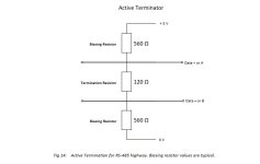
I like the technical papers from RS485.com (R. Smith !) and RobustDataComm. They're especially useful to explain why "two-wire" is never really just two conductors.
 
HI guys:
I am attaching several diagram from several sources, it seems to be that there is no such a wiring standard for modbus RS485 RTU.
In some cases A wire is (+) an in other cases A is (-), and the same for wire B, some vendors do not mention A or B but TX+ or TX-.

Why such differences exist ?

That makes non sense.

thanks,

widelto
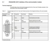


typically b is + and A is - but I have run across some devices that are A+ and b -.
 

Similar Topics

I have programmed servos from a handful of variety of manufacturers and series. Each time I used a PLC without motion functions. I have not worked...
Replies
9
Views
700
Hello, I'm am engineer for a plastic manufacturer. We swapped out a oem motor with one of equivalent nameplate stats made by marathon on our roll...
Replies
3
Views
480
I am trying to implement a sfift-by-wire on a vehicle and for that I am using a standard servo motor...
Replies
0
Views
313
Had an interesting experience this morning. An old Panelview 600, 2711-K6C5X series B to be precise, comes up as error 32. Unfortunately it...
Replies
0
Views
204
I have a GuardLogix PLC with safety inputs of HMI, Estops, Light Curtains, and Gates. Is it considered safe for the safety program to monitor the...
Replies
11
Views
768
Back
Top Bottom