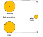
Unwinder

Your going to have your hands full (as they say) with this system

I would start with the winder controlling your speed through a full roll build
Just put the unwind in a low torque control mode (for testing above) or keep the unwind off and pull through the gearbox until the winder is working properly

Or you will fight both systems

Typically there’s a nip roll between the unwind and winder to isolate the tension zones between unwind and wind

And your probably going to have to connect the dc bus to both drives together

My take on it
 
Last edited:
If I understood correctly, you say you know the initial full diameter of the unwind roll, and also the (final?) empty diameter of the unwind roll.

Is that empty diameter the same as the core diameter?

Do you know the total (linear) length of the material initially on the unwind roll?

If the unwind control somehow maintains constant torque on the unwind shaft, then linear tension will increase throughout the process, and you may end up with roll formation problems e.g.telescoping. I think you want tension to decrease throughout the process, linear with length, IIRC, or perhaps with diameter (I forget which it is; my brother knows).

N.B.This assumes there is no nip isolating tension zones between winder and unwinder.
 
Last edited:
The linear speed to feed the material has to be constant in meter per minute.

How are you controlling the linear speed of the material? E.g. is the unwind motor going to control linear speed of the material, or is the unwind going to follow a linear speed that is controlled by something else?

What is controlling the winder motor(s)? And how is it being done e.g. torque control, speed control?
 
Last edited:
How fast does this thing go; what is the gear ratio between the unwind motor and unwind spindle?

Are you using a differential shaft on the rewind?

If this is a slow machine (<500 FPM) then the amount of gearing you have on the unwind may prevent you from effectively using torque control as a reasonable tensioning method unless your tensions are relatively high. Backdriving reducers requires torque that you have no control over. If this torque is greater than the torque required for the tension you intend to run you will have an issue. The torque required to backdrive a reducers is dependent on the reducer type and the ratio.

If you are using a differential shaft on the rewind then you will probably want to flip the concept around. Use the differential shaft to determine your tension and use the unwind to set a rough linear speed. You should have more forgiveness in your system that way. If you are slitting a 2 meter roll down to 200mm strips you will have 10 strips to deal with. Unless this material is very flat you run the risk of building rolls of slightly different diameters. If they are tied to a common rewind shaft the larger diameter strips will carry the tension and the smaller diameter strips will lose tension, possibly to the point of going slack. It is this specific case that differential coreshafts were designed to address.

You do need to be concerned with the wind tension profile as drbitboy indicated. Constant torque at the unwind will result in increasing tension as the rewind roll builds. This is very seldom a good thing. At a minimum you want constant tension through the rewind roll build. Many products will run best with a decreasing tension through the rewind roll build. I have seen VERY few cases where increasing tension through the rewind roll build is beneficial.

And then there is the slitting aspect. Assuming this is a shear style slitter you will want the slitter to operate at a slight overspeed. 3%-5% above web speed is typical. This means that whatever is controlling the material speed needs to be accurate to within about 1% over the whole run range to have any hope of staying within 3%-5% of slitter overspeed. The slitter will obviously work with greater than 5% overspeed. You may have compromised slit quality, however.

As has been stated already, if you have a way of entering initial unwind diameter and web caliper AND you have a way to measure length you can calculate running diameter. But unwind applications are VERY sensitive to all the values in this calculation.

Now for an opinion. You really don't want to attempt this with the components you currently have unless the material you are running is VERY insensitive to tension. From the sounds of it you have no way of measuring actual web tension, you have no way of measuring actual web speed, you have no way to effectively set web speed and you have no way of measuring either unwind or rewind diameter. If the rewind is running with a differential coreshaft then you have at least a chance. Otherwise you will really need to look into adding some hardware to this system to get it to work well...UNLESS the web is so tough that you can't possibly tear it with the drives you have. In that case, estimate rewind diameter based on material run and caliper. Set the unwind speed command to zero and operate the unwind drive at torque limit. Calculate the unwind diameter based on the rewind spindle speed, the calculated rewind diameter and the unwind spindle speed. Use that to modify your unwind drive torque limit to maintain something near your desired tension.

Good luck.
Keith

Life is much easier when there's PaceSetter in the middle..we used to use a nip point, or gripping knife roll.
Life is also much easier when you have motors that develop full torque at near zero speed. Those are not AC motors, if you haven't figured that out yet.
 
I assume you need cutting accuracy, right? If so - then you need to accurately know the roll diameter at all times. If that's the case - then you need an encoder roller with a known diameter and your AC Drive needs absolute position encoder with an encoder card that is optional on your Powerflex 527. Then based on the two - you can figure roll diameter accurately and that will give you the product length. It cannot be done in any other way. This is the only way.
 
I do not have an accumulating length measurement but I know the line speed. I do not have an encoder but I have a sensor in the winder pulley so I can calculate the line speed.
...
I am trying to control the linear speed of the unwinder. Currently to control the VFD 527 you can use motion commands.

Maybe I am naive, and we are overthinking this, and all OP is actually asking for is a feedback control loop using the pulley sensor data? The unwind motor speed is going to smoothly increase after the initial start, so even a simple floating control on the bottom half of a deadband might solve this. Or perhaps a speed ramp with a variable, slowly increasing slope (which is a model of the reciprocal of diameter, or similar)?

@ELGC/OP: I think we are almost there, if you could list all of the signals coming into the PLC, and all the controls going out, and the PLC model number, and answer the questions below, that should finish the data gathering step.

Most PLC programs are a model of a physical process, they don't model every atom and photon, but they model what they can from the available input measurements, physical laws and principles, approximations assumptions, etc. The primary design choice is the fidelity of the model to the physical process, and that is usually limited by the available inputs.

For example, in an earlier post you wrote that you were going to develop a table of diameter vs desired speed vs time. That is a model of the process, and you are probably going to do it in a spreadsheet. For my money it would be more flexible to code that model's equations into the PLC to execute in real time. So if a run comes up that is not in your table, or the process changes e.g. the motor acceleration capability on startup, then you don't have to go back to the spreadsheet.

0) What is the ultimate goal here? Is it to be able for the PLC to continually have, or calculate, a target speed that can be converted to a series of motion commands in real time?

0.1) What level of PLC skill do you possess, and what level of help are you asking for? E.g. some prototype PLC code you can tweak and insert into your program? Or the equations for a model that you will convert to PLC code?

1) What is the range of the values (diameter, line speed, etc.) you expect to see? What level of accuracy is needed for the unwind speed control (1%? 10%? 0.01%)?

2) How is the line speed calculation made from the sensor on the pulley? If the sensor is sending pulses to the PLC, one per some fixed length, then that could be also used to acculturate length for the diameter model. Even if not, the speed calculation result could be numerically integrated at regulator time intervals to model an accumulator.

3) I am a noob to motion controls, but I have seen other posts where VFD/motor combinations have been used for position control. Could someone point me to a link about this, or give a rough description of what is going on, or what these "motion commands" are and how they work, what issues them, over what medium/protocol, etc.?
 
I picture the system like this

It will be a trick to keep the speed and tension constant with his current i/o

unwindwind.jpg
 
Last edited:
Originally posted by ELGC:

I do not have an accumulating length measurement but I know the line speed. I do not have an encoder but I have a sensor in the winder pulley so I can calculate the line speed.

This is only true IF (and this is a big if) you know the winder diameter. You say you are calculating line speed from the winder "pulley". I assume you mean the coreshaft. So your picture of line speed is based on winder diameter. Since you aren't measuring the diameter you must be calculating the diameter...presumably based on some relationship to line speed...which is calculated based on winder diameter. See the issue?


Originally posted by drbitboy:

The unwind motor speed is going to smoothly increase after the initial start...

True, but at what rate? How do you know the rate is correct? If you are off just a little bit you will either tear the web in half or it will go slack. in a surprisingly quick hurry as a matter of fact.


Originally posted by drbitboy:
3) I am a noob to motion controls, but I have seen other posts where VFD/motor combinations have been used for position control. Could someone point me to a link about this, or give a rough description of what is going on, or what these "motion commands" are and how they work, what issues them, over what medium/protocol, etc.?

The OP states he is using a Powerflex 527, which is the CIP Motion variant of the Powerflex 520 series. The same control structure as the other 520 series drives, just a different command methodology. However, in the end I would be surprised if the OP uses anything other than a Motion Axis Jog and a Motion Axis Gear in this application. But again, the object is to create a linear motion from a rotational element with a constantly changing diameter. Without some external confirmation that your model is correct it is very hard to make this work. The OP states that the caliper is "constant". In 30 years of doing this stuff I have NEVER seen a roll with a truly constant caliper. If you are lucky the caliper will average across a relatively short span. But it probably won't be what you used for your calculation.

Using two speed based variable diameter axes without actual web monitoring is very difficult to make work. Not because the math and physical implementation at so hard. Its because the real world values very seldom match what you are using as coefficients in your math. I'm not sure how far down the design path the OP is but if I were designing this and the customer said I couldn't include a pull roll I would remove the motor from the unwind and add a brake. Calculate rewind diameter based off of initial diameter, caliper and length based on integrated speed. Calculate unwind diameter based on integrated line speed and a single pulse per revolution sensor on the unwind spindle. Torque based spindles are much less sensitive to diameter than speed based spindles. At least this way you won't run the risk of two speed based axes pulling against each other until the web breaks or having the web go completely slack.

Keith
 
He mentioned a 2 meter wide roll
I wonder what the core and max diameter of the unwinder roll will be.

and if the operator is stopping and starting for small rolls (after being slit) at the winder end

all important data
 
Argh, I did not notice the qualifier "winder" on pulley!

Yes, if that "winder pulley" is the winder core, then of course we need diameter, from an external source, to get line speed.

I had assumed it was a separate pulley with a fixed diameter and a surface that moved at zero speed* relative to the web.

* And yes I realize that this no-slip assumption is a risky one as well. It all boils down to the assumptions the model has to make when it cannot make measurements.
 
Last edited:
The tension will vary. Depending on type of material he's cutting, the momentary speed on each roller will differ. In film control applications, where film is used for packaging free rolling unwinder is usually hooked up after tensioning device with a springload and a limit switch. Typical tensioner has 2 or 3 rollers and material travels around them pulling them together. Having to have an unwinder motor is unusual and suggests much higher forces in the machine. Problem with something like that is there never is enough information to go with, and the guy is never going to tell us everything. But based on what he said already - I think that each roller has to have its own speed measurement - winder motor because it needs to have control over how fast the material is going and it needs a precise figure. So the control panel speed adjustment would work such, that the speed setting would require PLC to match the roller speed measurement on winder drum. VFD would accelerate until the speed was met and vice versa. While the unwinder needs its own roller measurement so that it can take the material speed to calculate its own speed. Makes sense?
They also need some sort of tensioning relieve mechanism, with sensors, to make sure the rollers don't rip the product apart. The tension control would be on the unwinder motor side or at least that's how I would imagine it.

I am writing this because it was said above that the speed is a known value.
I question that. Speed without measurement is never a known value. That speed measurement of a pulley is unclear. The only good measure is a roller encoder. That gives a precise figure taking into account material slippage. There are also factors like motor slip affecting the speed and having a two motor application like this is not an easy control system.
 
Last edited:
I'm a ChemE by training. Most project models boil down to conservation laws: Accumulation = In - Out (= Gaintas - Gazoutas;)); you can feed, remove, generate and accumulate, nothing else.

Pressure is an accumulation of a compressible (typically) fluid (e.g. gas or vapor) in a fixed volume.

Temperature is an accumulation of heat (or of energy, or of atomic and molecular vibrations).

Level is an accumulation of an incompressible (typically) fluid under the influence of gravity in a volume with fixed (typically) horizontal) cross-sectional area.

I have never done an unwind/wind project myself, but I have had my brother describe quite a few to me (1500-2500fpm, IIRC), including helping him with the geometry and mechanics of one controlling the net tension profile over a winding operation with a hydraulic cylinder applied against the variable weight of a wind roll on an arm at an angle from vertical, where that angle also varied during the process. In the end it seems to be the same thing: decreasing accumulation on the unwind; increasing accumulation on the wind; droop or dancers or an accumulator or summat else in the middle; plus some math to keep track of it all.

That's a long way getting around to say, in agreement with @kamenges,

you will either tear the web in half or it will go slack. in a surprisingly quick hurry as a matter of fact.

that whatever the specific application, accumulation can be neither less than zero nor infinte. So I don't see any way that there can be more than one independent speed-based axis between accumulations in any winding process. Meanwhile, in this thread, it appears that OP has been told "here is the process as designed and built," and asked "please control it."

The window dressing is different, but in the end you measure what you can, and model the rest.
 

Similar Topics

Hello Folks, This is the design idea of a hydrogel coater that I am working on. Unwind>>Coat hydrogel>>Rewind Spces: 300mm wide web. 6000mm...
Replies
13
Views
4,352
Hi, I am working on printing inspection machine where 3 nos. ACS550 of smaller rating less than 7.5Kw on unwinder, main motor and rewinder but...
Replies
6
Views
2,950
Hello guys, I am trying with diferents ways for compute the actual diameter of steel strip that is unwinding and winding. I see there are many...
Replies
3
Views
1,754
Hello All, on my aplication 1-from siemen plc with aif setpoint send lenze drive with torque control value:-10% 2-send speed limitation -5%...
Replies
5
Views
2,583
I need some suggestion for calculations for an intermittent unwinder. The system consists of a servo controlled nip roller that moves film to a...
Replies
7
Views
3,614
Back
Top Bottom