G Data file Configuration 1747BSN Back up scanner

SaadAlbehige

Member
Join Date
Dec 2014
Location
Libya
Posts
15
Hello guys

Thank you all for your support.
I have completed re-writing a program as it was lost and no back up file found.
Now the three PLCs are on Run mode . Two of them are ESD redundancy, which are connected to RIO via adapter.

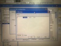
The two ESD PLCs have 1747BSN back up scanner. I tried to configure it until I reached G fiile they were displayed in decimal not structure mode as the RS logic is an old version.

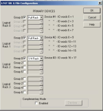
I set it up randomly see the pic, it is on Run mode now, am afraid that it does not scan all the RIO on the program? Any one explain to me how to configure it properly. I would be so grateful.
Big thank you in advance
FCBE1D8F-D805-49C7-98C7-D71D4863EB0C.jpg
 
Last edited:
You have quite a challenge ahead of you: most systems that use Redundancy are complex and control hazardous processes, and should be programmed and maintained by experienced and qualified persons with the appropriate tools.

Your RSLogix 500 can probably show the values in their structured format. There's a note in the 1747-BSN user manual (1747-UM010B) on Page 5-3 say indicates that the setting of the M0/M1 file actually enables the non-generic view:


For RSLogix 500 version 5.50 and later, configure the 1747-BSN M0/M1 size for 5548 words so that this non-generic G file configuration screen appears after you click on the configure G file button.

For RSLogix 500 versions prior to 5.50, configure the 1747-BSN M0/M1 size for 5547 words in order for this non-generic G file configuration screen to appear after you click on the configure G file button.

When I set my RSLogix 500 v12.0 for M0/M1 files of 5547 words, the Decimal/Hex generic configuration comes up, and I entered your values. When I set it back to 5548 words, the structured display came up with:

Rack 0: Full Rack
Rack 1: Full Rack
Rack 2: 1/4 Rack
Rack 3: Not Enabled

To figure out which devices occupy what I/O memory words, you'll have to very carefully examine and document all the RIO adapters.

G_File_Structured.PNG
 
Thank you very much for your reply.

As I have one adapter installed in a chassis along with four digital input and two output cards. This adapter is then connected to two ESD PLCS.

Would you please clarify to me what the manual means by Rack0 Rack 1 Rack 2 and Rack 3. I understood from the manual what full Rack, half Rack occupation … means. I could not get what Rack 0,1,2 and 3

In other words, I could not correlate Rack0,1,2 and 3 !

[Note[/B]: the Rack where the adapter is installed named Rack3, does this mean I should configure Rack 03 in G file, which you confirmed it was not enabled

Await your reply .

Can’t thank you enough for your reply.
 
The A-B Universal Remote I/O system originated with the PLC-2 and PLC-5 controllers, where an 8-slot physical chassis was considered a "Rack".

So the addresses for those are numbered, starting with zero.

The physical location of the chassis doesn't matter: it's a network after all. But the "Rack Number" correlates directly to the position of the data in the I/O table of the PLC or the scanner device.

RIO quickly became more complicated: you had 16-slot chassis, so they took up two "Racks" of memory. Or you had FLEX I/O, which could use up as little as 1/4 Rack of memory for two modules. There are data density settings (half, one, and two-slot addressing) and complementary addressing as well. And the PLC-2 and PLC-5 number everything in Octal, while the SLC numbers them in Decimal !

If you have an "ASB" adapter (1771-ASB, or 1747-ASB, or 1794-ASB) connected to this system and the adapter is configured for Rack 0, its data should show up in the 1747-BSN's I/O memory (for Slot 1 of the PLC) in the lowest numbered words of the I/O image.

The user manual is important, of course, but the basic layout is:

I:1.0 Rack 0 Slot 0
I:1.1 Rack 0 Slot 1
I:1.2 Rack 0 Slot 2
I:1.3 Rack 0 Slot 3
I:1.4 Rack 0 Slot 4
I:1.5 Rack 0 Slot 5
I:1.6 Rack 0 Slot 6
I:1.7 Rack 0 Slot 7

I:1.8 Rack 1 Slot 0
I:1.9 Rack 1 Slot 1
I:1.10 Rack 1 Slot 2
I:1.11 Rack 1 Slot 3
I:1.12 Rack 1 Slot 4
I:1.13 Rack 1 Slot 5
I:1.14 Rack 1 Slot 6
I:1.15 Rack 1 Slot 7

And so on for Rack 2 and Rack 3, up to I:1.31. The Output data table is similarly offset.
Most "ASB" adapters are configured with DIP switches. You need to examine the device very carefully and look up what the DIP switches mean.

Because the RIO technology has been around for so long, you often even need to know what version of a specific part number you have: a 1794-ASB Series A has different DIP switch settings than a 1794-ASB Series E.
 
Thank you so much for the clarification and your thorough reply.

Ok. What I will do tomorrow is , refere to the pic,
I will disable Rack0 to 2. I will enable Rack3 and configure it as follows

Either
Rack3 Group 0 1/4 Rack
Group 2 1/4 Rack
Group 4 not used
Group 6 1/4 Rack

Or

Rack3 Group 0 1/2 Rack to occupy Group 2 as well
Group 2 ——-
Group 4 not used
Group 6 1/4 Rack

Note: I need the back up scanner to scan all these I/Os

Does this make sense? If not, please let me know

49091AA8-F26F-4D21-AA59-FB8765218020.jpg
 
Thank you for that photo !

there is very probably some confusion between the term "Chassis" and the term "Rack".

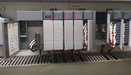
The label above that chassis says "ESD PLC RACK 3". I cannot tell if it is addressed as "Logical Rack 03" in the RIO network protocol, or if it is simply labeled "Rack 3" because there are two chassis for the backup CPUs and this is the third one in the layout.

You need to (power down first) pull out and examine the 1747-ASB adapter and read its user manual to figure out how it is configured.

The DIP Switch settings are described in the Installation Instructions for that module:

https://literature.rockwellautomation.com/idc/groups/literature/documents/in/1747-in014_-en-p.pdf

Because the chassis you posted a picture of has either 9 or 12 I/O slots, it is going to take up more than one "logical rack" of I/O memory. Based on the earlier configuration information, it is my guess that it takes up Rack 01 (full rack) and Rack 02 (1/4 Rack).

But that is ONLY a guess. If you are confident that module has not been swapped or replaced or modified, then examine it and you should be able to tell where in the SLC-500 I/O memory this chassis and its I/O modules will be represented.
 
Last edited:
One more thing:

I don't know you or your experience and skill, but I am going to repeat my recommendation that emergency shutdown systems are not appropriate for novice engineers and technicians to work on.

I cannot emphasize strongly enough that it is imperative to know what you are doing before working on a safety-critical system. Literal lives depend on your work, including your own.
 
Last edited:
Thank you so very much. Things are much clearer now.

I have checked the adapter DIP switches, it’s logical Rack 0 , Logical group start is zero, and density addressing is one slot.

I set up the G File accordingly.

Big thank you to you.

Highly appreciate your help.
 

Similar Topics

I stumbled onto this behavior the other day, then went looking for old forum posts with the assumption that "there is nothing new under the...
Replies
0
Views
776
Hello everyone, Does anybody know if it is possible to read the Free Memory words of a PLC5 from a status register? I have a feeling it may not...
Replies
1
Views
1,012
Hello All, I am working on converting a program written in RSLogix 500 to Connected Components Workbench. The MicroLogix to Micro800 converter...
Replies
1
Views
1,192
I am looking for a profile sensor that I can get access to the raw data. I looked a Keyence, Cognex and can probably get what I need but they are...
Replies
14
Views
7,208
Hello all, Data logging in factoryTalk view has stopped suddenly, i cannot able to find the reason. Then i tried creating new datalog models...
Replies
3
Views
1,594
Back
Top Bottom