Message I/O module directly

tlf30

Lifetime Supporting Member
Join Date
Apr 2021
Location
Deadhorse Alaska
Posts
185
Hello,
I was wondering if someone can help me solve how to use a MSG instruction to get the data and fault information from an ControlLogix I/O module.

I am interested in sending the message from one controller to the I/O module of another controller to periodically get the fault bits from the I/O module, and ideally the data bits. For now let's just focus on the 1756-IB16 for simplicity. If I can just grab the entire input data structure, and parse it myself, that would be fine (actually ideal).

I looked in the EDS file, I see that the connection paths are:
"20 04 24 10 2C C5 2C 83" for time stamped data
"20 04 24 10 2C C5 2C 83" for standard input data

But I am not sure how to use this information to configure the MSG instruction to pull the data.

If someone could guide me through how to get the MSG parameters, so I could extract them for this module and others, I would really appreciate it.

Thank you,
Trevor
 
From what I gather, the path is decoded as follows:
"20 04 24 02 2C C6 2C 82"

20 04 = Class 0x04
24 02 = Instance 0x02
2C C6 = Attribute 198 (output data)
2C 82 = Attribute 130 (input data)

But I always get an unsupported service requested error. I have tried with services:
0x01 - Get All Attributes
0x03 - Get Attribute List
0x0E - Get Single Attribute
 
Welcome to the PLCTalk forum community !

I thought for sure this had to be a simple path or radix issue but my attempts to reproduce your messages fail with the same error code.

It's possible that RA really does not support Get_Attribute_Single (0x0e) or the Assembly object specific Get_Member (0x18) service for these modules.

One reason may be to prevent a similar technique to what you're doing: a sort of user-application-mode redundancy. There are real redundancy systems for a reason !

Ordinarily if you wanted to read the Input data and fault data from a 1756 module owned by a different controller, you would configure a Listen Only connection to the module. That would get you the data cyclically and in the customary format, and can be done in Run mode for most modern controllers.
 
Oh, and not-seeing-the-forest-for-the-trees: The controller that owns the 1756 module will have a well defined Local:Slot.Element sort of tag that you can read with the other controller with a MSG command.
 
Thanks Ken,
My goal for this is to mainly get the fault bits. We have several hundred ControlLogix PLCs, and I am working on a PLC program that will grab diagnostics info from each PLC and organize it into a UDT array to I can display it on the HMI. I have figured out how to get everything but the I/O module per channel fault bits. I do not want to modify the programs on each of these PLCs, nor mess with trying to pull the info from tags in the PLCs.

I have code in place that uses class 0x69 to traverse the I/O tree from each controller to get the CIP path to each I/O module. All I do is give my program a string array of CIP paths to each controller. I am running a 'who' message to each module and getting the basic information for it, for controllers and communication cards I am using other messages to get more in-depth diagnostics information. I am also grabbing info from the backplane such as the number of slots it has.

Do you know if there is a way to create a listen only connection and pull the data via a message instruction? I tried to create a message with the connected flag set to true but it always returns that is failed to connect.

Thanks,
Trevor
 
My understanding is that, with a listen-only connection, you would just add the IO module to the IO configuration of the diagnostic PLC. You would then have all of the tags right there in your project. The other PLCs wouldn't need to be modified at all nor would you use MSG instructions.
 
My understanding is that, with a listen-only connection, you would just add the IO module to the IO configuration of the diagnostic PLC. You would then have all of the tags right there in your project. The other PLCs wouldn't need to be modified at all nor would you use MSG instructions.
That would work well for a handful of PLCs but if the OP has several hundred PLC's and their IO modules to monitor, the IO configuration may/will be too large for his PLC of choice to gather the data into.
 
That would work well for a handful of PLCs but if the OP has several hundred PLC's and their IO modules to monitor, the IO configuration may/will be too large for his PLC of choice to gather the data into.

Yes, unfortunately that is correct. There are thousands of IO modules, and it is not feasible to hard code each one, especially when some of them are not able to be added online like PointIO.
There are just too many points to go with a tag based approach. That is why I developed the code to automatically build the CIP paths for each module by querying the controller's IO tree.
 
There are just too many points to go with a tag based approach. That is why I developed the code to automatically build the CIP paths for each module by querying the controller's IO tree.
So you're querying class 0x69? I can help.

Also, you can find module connection information the controller uses to establish comms here:

C:\Program Files (x86)\Rockwell Software\RSLogix 5000\Module Profiles

A cursory look through them didn't reveal anything beyond the IO assemblies you're already looking at, so you might try querying the CIP common objects for the Discrete Input (0x08) or Discrete Input Group (0x1D).

You have me curious (again) so I'm going to see if I can parse point info from my 5069 chassis.

edit:
5069-IB16, despite being identified as CIP General Purpose Discrete IO, doesn't appear to implement the optional Discrete Input Point or Discrete Input Group objects.
 
Last edited:
Hello Jeremy,
Yes, I am using class 0x69. In the folder C:\Program Files (x86)\Rockwell Software\Studio 5000\Logix Designer\ENU\v34\Bin\Comm contains ADF files. These files describe the structure of many CIP objects (but not all).

You can construct the IO tree using the following attributes:
8 = Link Parent
9 = Link Port
10 = Link Address
18 = Long Link Address (for ethernet IP address)

You can then construct the CIP path to each module.
You will need to scan the class instances from 1 to the max instance returned by the class. I have not found a way to get a list of the valid instance ids. It only responds to service 0x03 (Get Attribute List).

Thank you for testing on the 5069 IO. I tested on the 1756 IO and did not have any luck with the discrete input point or discrete input group classes either.

I'm beginning to wonder if the only option is to build my own IO scanner block, but would really like to not do that.

EDIT: I also tested the safety classes 0x3D (Digital Input Point) and 0x3E (Digital Input Group). I was using service codes 0x01, 0x03, 0x0E on both the class attributes and instance attributes to try to get anything to return. The module I am testing against is a 1756-IB16IF.
 
Last edited:
0x69 is the collection of IO objects across all CIP port types (backplane, ethernet, etc.).

Service 0x4B is what you're looking for. A message to any Instance Id will return the partial list of Instance Ids including the requested Id (if it exists) followed by the next valid Instance Id. If it doesn't exist, you just get the next valid one. Each Instance Id is 4 bytes. If you start at 0, you can COP the first 4 bytes of the response into a DINT/UDINT and you'll have Instance 1 (the host controller), for example. You can quickly iterate the list until your message DN_LEN is equal to zero. You can even more quickly iterate if you use the last Instance Id provided in the returned partial list as the base Instance Id of your next request.

Attribute 4 is EntryStatus (value is same produced by a GSV)
Attribute 9 is PortId
Attribute 10 is Slot (used if the IOMap instance is to a backplane device (PortId = 1), zero otherwise)
Attribute 14 is InstanceId (value is same produced by a GSV)
Attribute 18 is Link Address (IP address alone, if applicable)
Attribute 31 is EPath (this can be directly copied to a message instruction's path)

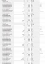
I attached a screenshot from my own setup. ST_Sys_Node is a made-up class of objects containing an IOMap instance, its parsed Identity, and Name. Identity is retrieved by using the EPath. Name is retrieved by querying the Logix symbol table (class 0x6B) using services 0x01 and 0x03 for instances of TypeId 4201 (name string is returned and prepended with "Map:" that I scrub). Overall list is kept sorted by EPath.

I reached out to Rockwell and they never complained about me doing this.

LogixNodes.jpg
 
Last edited:
Thank you for the amazing info. I just tested and using service 0x4B works great.
I am interested in the Logix symbol table. If I can extract the symbol(s) for the module, then I can get the IO fault info from the UDT via a standard read symbol message.
I am going to start playing with that.

I really appreciate the information. Can you share where you came across that info? If not I completely understand.

EDIT: Is there a way with service 0x4B to specify the max number of entries returned?
 
Last edited:
Thank you for the amazing info. I just tested and using service 0x4B works great.
I am interested in the Logix symbol table. If I can extract the symbol(s) for the module, then I can get the IO fault info from the UDT via a standard read symbol message.
I am going to start playing with that.
The Symbol Class (0x6B) table doesn't contain anything specific to any one functional aspect of the controller. It's a pseudo relational database of the names of types or objects that are used throughout - tags, node names, AOI names, UDT names, program names, and so on. Each tuple has a Type describing its use - whether part of the IOMap, Data Table (tags), etc.

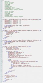
Symbol look up is a bit involved. You would start with service 0x03 and send 8 bytes to instance zero. I use the form SINT[8] for the request and SINT[512] for the response:
Code:
SymReq[0] := 3;
SymReq[1] := 0;
SymReq[2] := 1;
SymReq[3] := 0;
SymReq[4] := 2;
SymReq[5] := 0;
SymReq[6] := 3;
SymReq[7] := 0;

This lookup to instance zero will return the max symbol Instance Id at SymResponse[12]. I then use service 0x01 upon the class iteratively until hitting the max Id.

Each response will produce:
SymResponse[0]: Type (UINT)
SymResponse[2]: Address (UDINT)
SymResponse[6]: "Offset" (UINT) but really a 2-byte version of .LEN of the final string.
SymResponse[8]: Name (SINTs of length "Offset" corresponding to Data[0]...Data[Offset-1] of the final string.

To save you time, I attached the code I wrote for that part. Lines 298-310 are where the prepended "Map:" substring is removed from the module name.

My ST_Sys_Symbol UDT has:
- Instance (UDINT)
- Type (UINT)
- Address (UDINT)
- Name (STR_64)
- ObjectAddress (UDINT)

I really appreciate the information. Can you share where you came across that info? If not I completely understand.
An exhaustive effort in plugging service Ids into messages by hand into the vendor-specific classes (starting at 0x64), teasing out responses, and documenting, documenting, documenting to later compare results with other class responses. The free ODVA/Molex tool is good for this for many reasons.

EDIT: Is there a way with service 0x4B to specify the max number of entries returned?
Not to my knowledge.

SymbolClass.jpg
 
Last edited:
Symbols come into play in Studio when you use a tag name or such in instructions - internally the string gets resolved to an address in the Data table via lookup in the Symbol table when you compile. The Symbol usage as a string remains visible to the user.
 
Last edited:
I've been deep diving CIP for some time for a personal project and its underlying hints of ASN1 largely make me think Logix is just an ASN1 interpreter/factory. CIP is the mechanism by which an ASN1 node talks to another.

I was familiar with the .ADF files by the time of your original post. I now think it stands for ASN1 Definition File.
 
Last edited:

Similar Topics

Hi, I currently have 5 DH+ networks, each with approx 10 or so PLC5s on it. In order to communicate between each network a ControlLogix routing...
Replies
0
Views
3,471
Is there a way to add a local message display to Studio 5000 View Designer? If its there, I’m not finding it. I have used them in older versions...
Replies
11
Views
396
Hello, I made a change in alarm setup in factory view studio, where I changed a alarm message text. After that I made a run application and...
Replies
0
Views
126
I have a safety PLC AB that is stuck trying to charge the capacitor and will not do anything. No communication or anything can be done. Is there...
Replies
0
Views
66
Hello, Ive gotten a few answers on this from the Rockwell tech support but it's just not clear as they often point to the manual. I've also read...
Replies
0
Views
88
Back
Top Bottom