Help on PID control

40mpg

Member
Join Date
Dec 2021
Location
Oakland, CA
Posts
82
Hello all,

I have an issue with a PID block in RsLogix 5000.

The parameters are

P: 3.25

I: 0.11

D: 0.01

The Set Point is 71 psi

This loop has been used for over a decade. The problem is the PV never reaches the Set Point of 71, it hovers at 68-69 and cuts off. I've tried to increase the P, and it still hovers at 68-69. Lower I and D to 0 and it never goes pass 5 psi.

I am starting to think the valve ( the device the CV is trying to control) is starting to go bad after 16 years in operation.

The Output always maxes at 2 Volts ( 0 - 10 Volts).

Anyone have any suggestion on what I can do?
 
Um, lots of questions.

- Does the CV go to 100%?
- Does the valve open 100%?
- The system running full out, can it get past that SP?
- Is your scaled out good/right?

I think you can start there, and also... does it need to go past this setpoint or is this considered good enough. Might ask an old timer if they know the story, like the pipes burst if the PID goes past the setpoint at all.
 
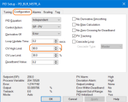
Check the PID instruction element CV High Limit setting to see if it is limiting the output to less than 100% If so, there is probably a good reason. If you adjust it upward, do it gradually and see if that allows the PID to raise the output enough to achieve the setpoint.

In case you didn't write the program, it is not uncommon to programmatically manipulate the CV High Limit which will be the ".MAXO" element of the PID tag. To find out, pull up a cross reference on the PID tag to look for destructive references to that member.

Get a screenshot if you can of the PID config page.

If you don't find it is limited at the PID instruction to around 20% (2 vdc) then chase down the tags that end up at that analog output point and ensure that the scaling is all correct (which could be in the card configuration depending on the hardware you're using).

rs5kpid.png
 
Last edited:
Hello,


The CV goes to 100%


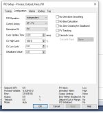
This is the config page


Check the PID instruction element CV High Limit setting to see if it is limiting the output to less than 100% If so, there is probably a good reason. If you adjust it upward, do it gradually and see if that allows the PID to raise the output enough to achieve the setpoint.

In case you didn't write the program, it is not uncommon to programmatically manipulate the CV High Limit which will be the ".MAXO" element of the PID tag. To find out, pull up a cross reference on the PID tag to look for destructive references to that member.

Get a screenshot if you can of the PID config page.

If you don't find it is limited at the PID instruction to around 20% (2 vdc) then chase down the tags that end up at that analog output point and ensure that the scaling is all correct (which could be in the card configuration depending on the hardware you're using).

Capture.JPG
 
Um, lots of questions.

- Does the CV go to 100%?
- Does the valve open 100%?
- The system running full out, can it get past that SP?
- Is your scaled out good/right?

I think you can start there, and also... does it need to go past this setpoint or is this considered good enough. Might ask an old timer if they know the story, like the pipes burst if the PID goes past the setpoint at all.


On the initial tune. I did get it to go to 71, which trigger a process. It needs to hit 71 for the process to start.


I'm perplexed , as the output card is configured to go from 0 V to 10V, but it max at 2 V on the output.
 
On the initial tune. I did get it to go to 71, which trigger a process. It needs to hit 71 for the process to start.


I'm perplexed , as the output card is configured to go from 0 V to 10V, but it max at 2 V on the output.

Two things:

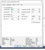
Your Scaling tab shows some odd numbers for CV Max and Min. Not sure I have ever seen a negative number there.

What value are you seeing going into the output channel and does it match what you measure with a voltmeter? Maybe there is a wiring problem or faulty analog output channel. Since it is a voltage output, you might disconnect the field wiring from it and see if the measured voltage changes.
 
Last edited:
Two things:

Your Scaling tab shows some odd numbers for CV Max and Min. Not sure I have ever seen a negative number there.

What value are you seeing going into the output channel and does it match what you measure with a voltmeter? Maybe there is a wiring problem or faulty analog output channel. Since it is a voltage output, you might disconnect the field wiring from it and see if the measured voltage changes.

Yeah its weird how they did this.

But the Low is 0 V and the High is -10 Volt

Volt meter reads -2V. Anyone seen this in the field where the Voltage reading is negative?
 
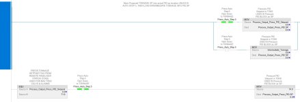
Please give me your thought on this band aide...


1. The operators found that when the Set point is set above 55 tons: the PV will always hover 3 tons BELOW the SP. For example, if the SP is 71, the PV will stabilize at 68, if the SP is at 70 then the PV will stabilize at 67 etcccc..


This is off of the PID values in the first post.


Sooooo, to get us by, I am thinking of forcing a value of 74 into the PID's loop SP when the user selects 71. This will not work for other SP values.


1. Process_Output_Press_PID_Setpoint is the tag that stores the Setpoint value indicated by the user


2. Process_Output_Press_PID.SP is the PID Loop's internal Setpoint tag

Capture.JPG
 
Please give me your thought on this band aide...
My thoughts are probably the same as yours: that I agree it's a band aid. Whether it's worth doing means weighing the cost of not reaching 71 for the time it takes to find the root cause.

TL;DR

That said, and with the caveat that I do not know the process so anything I say should be taken with a tonne of salt, I don't see the harm if it works and causes no safety or long-term sustainability issues. E.g. if the PID+process starts working "as designed," then is the process safe running at a PV of 74?

Also, before implementing that change, I would use an operator-entered test setpoint of 74 and see if the PV does indeed settle around 71 and "solve" the operational problem.

But something else is going on. If the PID - with non-zero Integral action - can find a CV output value to drive the process PV to a value at an offset from the SP, and can do so stably, but the PID cannot drive the PV to that same value by using it as the SP, then you have not solved the root cause of the problem. Where is the PV coming from? Is there some quantization effect, e.g. an accumulation measurement divided by a time measurement that enters a different regime around a PV of 55?

The solution you propose is limited in scope, and can easily be disabled for testing e.g. enter 71.01 as the setpoint, so it does not seem to be a huge risk. Personally I see little difference between that and adding 3 to any operator-supplied SP above 55.

But again, this is all speculative as I do not know your process.
 
Is there a non-zero deadband value set in the PID?

I'd be curious to see the contents of the Process_Output_Press_PID, including the .DATA[] array values, while the process is running stably with a SP of 71 and a PV of 68.
 
Last edited:
I almost always work with analog signals that are 4 to 20mA. I haven't worked with voltage references since the tire factory I left in 2006 and there they were almost always 0 to 10vdc.

I have never seen a valve positioner that wanted a 0 to -10vdc reference. Are we sure that is all right?

Wherever possible, I want my logic to work with the same units of measure I can see on my instruments and maybe they do in your case too. If there is requirement to scale something to or from raw channel digital values, or some other odd scaling I do it in one place per channel and only deal with engineering units elsewhere.

When the PID output is 100% are you seeing -10.0 going into your analog card channel data?

Is the card capable and set up for -10.0vdc?

How does what goes to the data going to the card compare with your multimeter? Does it jump if you disconnect the load?

I have a feeling that your issue has to do with something out of calibration or functioning incorrectly at or above a voltage level.

I notice in your screenshot of the PID that the PV is -2.539 so is the feedback signal also in need of calibration?
 
Last edited:

Similar Topics

So were commissioning all the PID loops I had programmed to work with the new wonderware HMI system that was installed. Got all but 1 tuned pretty...
Replies
3
Views
2,352
Allen Bradley PLC 5 What operations wants to do is as the Oil Flow rate (0-3000 m3/d) increases more chemical is injected into the flow line...
Replies
8
Views
2,492
Hi All, I have been asked to modify our contact tank pumping station controls. Currently pump speeds are manually entered (as %) by operators...
Replies
2
Views
2,226
Good Day, I have been programming for a while and a complete newbie in using a PID Control block. Now i am studying 📚 it using PC...
Replies
12
Views
4,575
I'm working on a PID ladder logic program to control a small process trainer as a college project. 2 valves in a split range setup control hot...
Replies
20
Views
5,154
Back
Top Bottom